
- Feature: an unfilled groove in parent metal at the weld boundary.
- Record: location, maximum depth, affected length and measurement limitations.
- Decision: apply the specified code, edition and service category.
- Repair: use the authorized route, then complete the required examination.
A narrow line beside a finished weld can trigger an expensive argument: the welder sees a small surface mark, the inspector sees missing metal, and production wants the member released. Undercut welding defects require a detailed account of the feature before any material is changed. The best practice is to first identify the feature, measure its extent, determine the applicable requirement, and note the status.
Undercut welding defects are unfilled grooves at the weld boundary in parent metal. Measure depth and affected length, then apply the specified acceptance rule. Repair and release require the project’s authorized disposition.
- Some undercut indications meet the applicable acceptance criteria; automatic repair can remove useful material.
- Instrument graduations and measurement accuracy are different quantities.
- Acceptance can change with code edition, loading and the particular weld toe.
- A smooth repair still needs dimensional checks and the specified inspection.
Undercut welding defects: recognize the groove
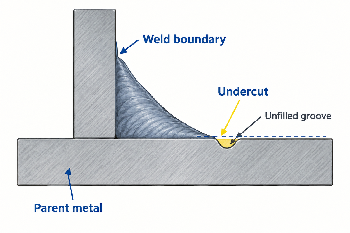
Undercut is a groove which has melted into the parent metal at a weld boundary and has been left unfilled. The notch removes some local section and changes the geometry of the load-bearing path. Considering the indication as a rejectable defect calls for an additional determination: assessing the condition versus the acceptance criteria of the weld joint.
What does undercut look like when welding?
Undercut is like a narrow channel which is adjacent to the toe of the weld and is found below the adjacent base material surface. It can be continuous or intermittent. After appropriate cleaning, an angled light helps to define the depression; a photograph is taken to record its condition, and a suitable depth measurement is taken to establish how far it extends into the base metal.
TWI’s geometric-imperfection guide mentions the parent-metal groove, and states it can occur on individual passes as well as the completed surface. In a multipass joint, an uncorrected recess beside a previous weld pass can trap slag inclusions. External undercut is present at the exposed surface; internal undercut at a root, however, may require a different type of inspection to determine its presence and location.
For an inspector encountering two similar looking marks, classify location before choosing the gauge. A depression next to the bead and a low center of the weld are two different conditions. The types of undercut may describe location or continuity; those labels do not supply an acceptance limit. Welding undercut is referred to by the absence of the parent metal, not by the color of the bead.
A 0.45 mm groove recorded over 35 mm describes an indication, not an acceptability level in service. Important factors like geometry, loading, and the remaining section, determine the engineering significance. The research by Niraula and Remes in 2025 studies local undercut and fatigue in butt-welded joints. The modeling results shouldn’t be applied as a universal fatigue-life reduction.
Causes of undercut: balance arc and weld pool
The main causes of undercut are conditions that cause the joint edge to melt faster than the molten weld pool refills it. Current and voltage, travel speed, arc length and electrode angle interact. Proper control of the welding process means correcting that balance within the approved procedure, rather than prescribing one lower-current setting for every position.
What causes an undercut weld?
Undercut forms when the edge melts and the weld metal fails to refill the resulting groove before solidification. Excessive heat at the edge, insufficient deposition, a long arc or excessive travel speed may contribute to Undercut. TWI also describes low-current insufficient fill; therefore, the diagnosis should also be made on the basis of the process bead and settings rather than high current alone.
Understanding molten metal flow and solidification aids the description of formation of undercut. Enough filler metal must reach the melted edge while the process retains the required weld size. Heat input by itself can’t clarify as to how the metal is distributed along the edge.
In MIG welding, voltage and wire-feed/current changes affect arc behavior and deposition together. TIG welding includes the relation of torch movement and separately supplied filler material. With submerged arc welding, we need to pay attention to electrode placement, flux delivery and fit-up. Welding techniques that work in one position may produce a different weld puddle in another.
Welding professionals investigating what causes undercutting should compare the actual weld edges with the specific welding procedure. A change that improves one toe may disturb the opposite toe. Undercut can occur intermittently, so retain the location pattern, as well as control-panel settings.
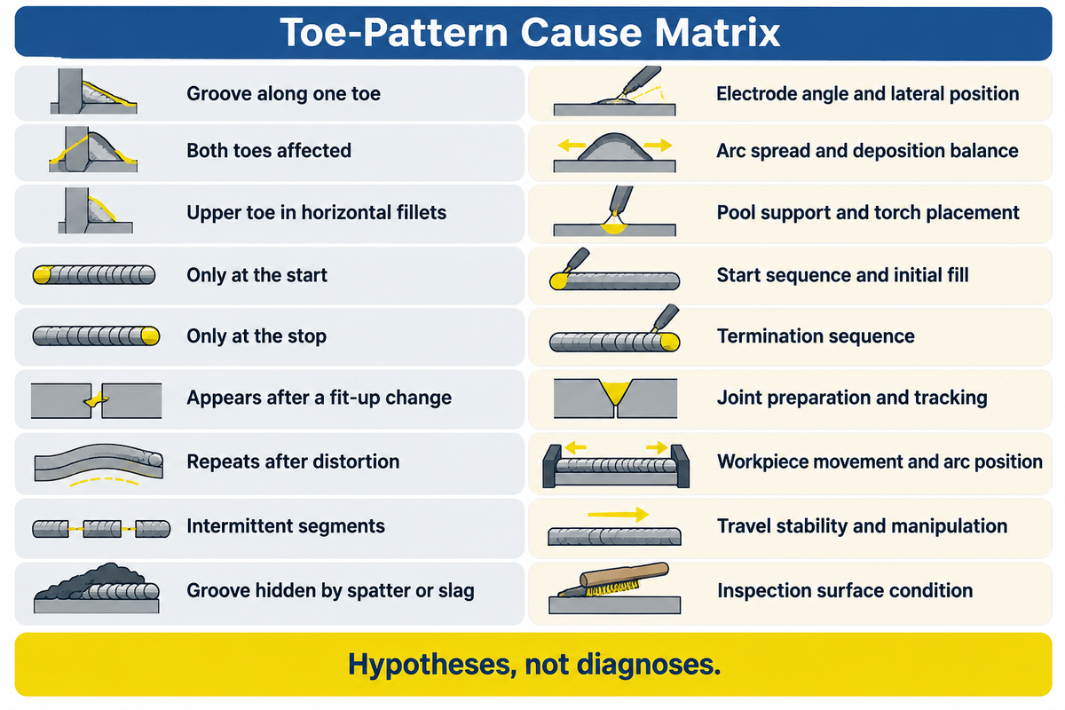
Toe-Pattern Cause Matrix
Use this diagnostic matrix to determine the next controlled observation. Each row is a hypothesis and not a diagnosis based on appearance alone.
| Observed pattern | Check first | Useful comparison |
|---|---|---|
| Groove along one toe | Electrode angle and lateral position | Opposite toe under the same run conditions |
| Both toes affected | Arc spread and deposition balance | Recorded settings against approved range |
| Upper toe in horizontal fillets | Pool support and torch placement | Actual position and changing joint geometry |
| Only at the start | Start sequence and initial fill | Start region versus steady-state region |
| Only at the stop | Termination sequence | Run-off location and completed end profile |
| Appears after a fit-up change | Joint preparation and tracking | Gap/offset record before changing settings |
| Repeats after distortion | Workpiece movement and arc position | Position record before and after movement |
| Intermittent segments | Travel stability and manipulation | Mapped locations against process log |
| Groove hidden by spatter or slag | Inspection surface condition | Cleaned profile, without grinding away evidence |
In an AWS-hosted submerged-arc discussion, an experienced practitioner described upper-toe undercut during beam fabrication, with fit-up, distortion and angle, among the checks. The account mentioned that angle wasn’t always the cause. In that context, observe the process and not define the specification.
For the example 35 mm segment, retain the original observation while making a controlled trial elsewhere. It’s hard to tell which change impacted undercut formation when multiple welding parameters are changed together. It’s better to compare which toe condition and which weld size are needed; reducing the groove by using an undersized bead does change the problem.
Undercut vs underfill, overlap and lack of fusion
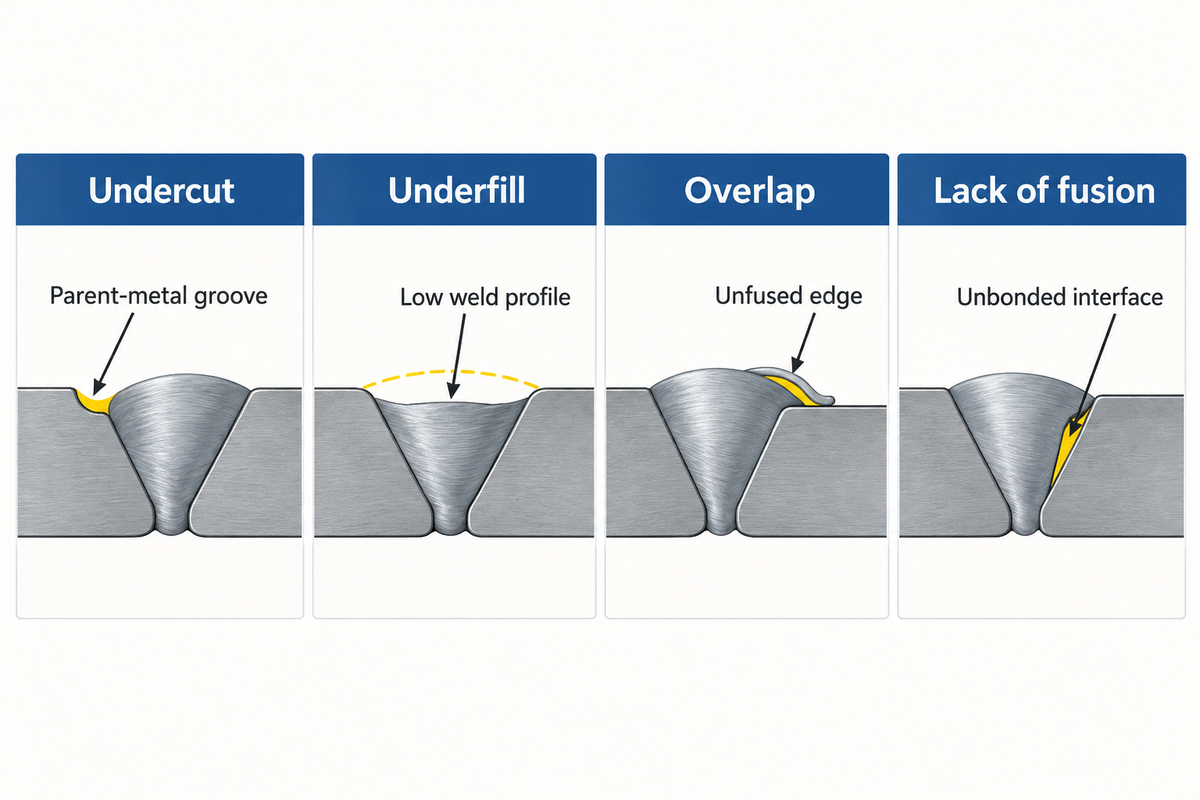
Undercut removes parent metal next to a weld; underfill leaves insufficient weld metal in the required profile. Overlap goes beyond the edge and doesn’t fuse to the parent metal. Lack of fusion is an unbonded interface and may lie within the weld. Classification matters because each type of defect calls for different measurements and inspection.
| Condition | Where to look | Decision consequence |
|---|---|---|
| Undercut | Groove at the weld toe or root in parent metal | Measure local depression and affected length |
| Underfill | Low surface within the weld metal | Assess required fill/profile separately |
| Overlap | Weld metal extending beyond the toe without fusion | Evaluate the unfused edge and governing criteria |
| Lack of fusion | Unbonded weld/parent or interpass interface | Use the specified inspection method and coverage |
A weld inspector can find undercut and underfill on a single weld. Calling “poor bead” loses information. For the difference between undercut and underfill, Paul Cameron’s welding terminology explanation is helpful. Tony Anderson’s discontinuity guide addresses incomplete fusion.
Porosity, cracking and slag inclusions are also common weld discontinuities. A gauge on an exposed edge of a weld does not clear the weld zone internally. The FHWA says undercut and rough weld bead profiles may give non-relevant dye penetrant results and that penetrant can’t determine subsurface defects. Indications should be interpreted using the prescribed examination method. Dye in a groove doesn’t necessarily mean a crack is present. Structural integrity requires the inspection coverage specified for joints.
How should you measure weld undercut?
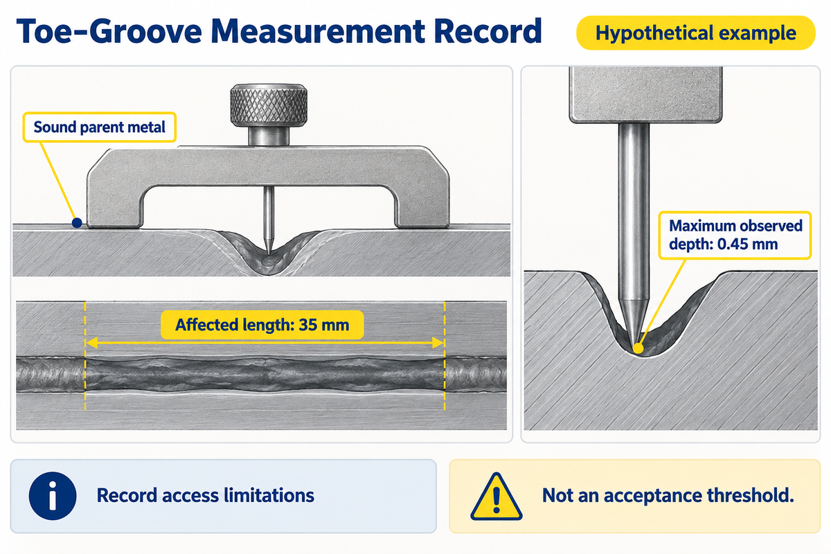
Measure the depth of undercut using a suitable gauge, referenced to the adjacent sound parent metal surface, and with the gauge’s probe seated in the depth of the undercut. Separately, map the extent of the affected area. Record the instrument and the condition of access so another inspector can make the same measurement. Near-limit or inconsistent readings need resolution under the project’s decision rule before release.
- Identify the member, weld and exact toe. Preserve the original condition and location before repair.
- Prepare the inspection area under the specified method. Remove obscuring slag or welding spatter without changing the groove.
- Check the gauge range, verification/calibration status, reference seating and probe access.
- Examine the affected region and record the greatest observed depth and the depth/length distribution required by the governing rule.
- Save the location sketch, readings, surface/access limitations and photographs with a scale.
The Niigata FDW-1 document lists 0–4.00 mm range, 0.01 mm graduations and ±0.04 mm accuracy; graduations aren’t total measurement uncertainty. The printed 2011 manufacturer document also describes a three-point adjustable base. Those are specifications of the named instrument, not a current calibration result for the gauge on your bench.
A good display can still provide a poor reading if its base rocks on scale or if its tip bridges a narrow recess. TWI flags mill scale, surface irregularities and spatter, as measurement problems. NIST says measurement uncertainty depends on the particular measurement and the representative working environment; therefore a gauge specification alone can’t prove a near-limit conformity decision.
Toe-Groove Measurement Record
Example: member B-17, weld W-04, flange side toe. The assumed observations below demonstrate a record format; 0.45 mm is not an acceptance threshold.
| Record field | Example entry | Why retain it |
|---|---|---|
| Location datum | From marked end A, 1240 mm | Find the same region later |
| Affected interval | 1240–1275 mm | Map the groove independently of total weld length |
| Affected length | 35 mm | Support the applicable length evaluation |
| Observed maximum depth | 0.45 mm | Preserve the greatest observed depression |
| Repeat at marked point | 0.44 / 0.45 / 0.45 mm | Show repeat readings, not total uncertainty |
| Gauge identity | G-02, FDW-1 | Connect readings to the instrument record |
| Instrument range | 0–4.00 mm | Check suitability for the observation |
| Graduations / stated accuracy | 0.01 mm / ±0.04 mm | Keep the two specifications distinct |
| Surface and access | Clean exposed toe; base seated locally | Record conditions affecting repeatability |
| Decision status | Hold for specified-clause comparison | Keep measurement separate from release |
Consider the example B-17 inspection at the end of shift. The production supervisor wants the member moved, while the inspector has three repeat readings at the marked point, but hasn’t resolved whether the gauge base seats properly with respect to the groove. A receiving photograph from procurement shows only the bead face. The useful next action is a hold tied to that particular measurement question; retain the location sketch, inspect the seating, and repeat as agreed. Grinding first would remove the original feature, and also leave the next inspector to reconstruct what was there. A recorded hold protects the observation while its interpretation is addressed.
Production may resist another reading when a display looks precise. The correct response is to retain the raw result and resolve seating, access or near-limit uncertainty with the designated inspector. It isn’t correct to mechanically add ± 0.04 mm to every reading as an acceptance rule. How measurement limitations are introduced into the decision is governed by the agreed inspection method. Restricted access to the weld area belongs in that record.
A 35 mm affected interval and a maximum observed depth of 0.45 mm answer different inspection questions. Reading increments of G-02 are 0.01 mm, and its stated performance is ± 0.04 mm. Keep all four values in the record rather than reducing them to “minor undercut.”
Acceptable amount of undercut: choose the governing rule
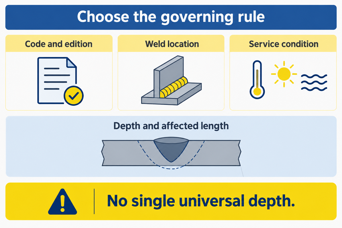
The acceptable amount of undercut comes from the fabrication code and the project specification pertaining to the relevant edition and application category. The thickness of the base metal, loading, toe position, and accumulated length impact comparison. A copied number from a different application can produce an incorrect decision, even with the correct depth measurement.
How much undercut is acceptable in welding?
No single depth is acceptable for every welded product. Use the limit for the specified code edition, weld location and service condition. Compare the required depth and length observations. For a structural member, the designer’s loading category, and the requirements of the Contract pertain to the decision; a shop rule of thumb can’t be substituted for them.
AWS July 2025 reports changes to undercut tolerances and conditional grinding treatment in D1.5:2025 compared to 2020. These depend on toe, stress orientation and remaining section. This bridge specific development is a good example of not blindly following a D1.1/ pipeline or other project number in an H-beam order.
The public ISO 5817:2023 abstract gives workmanship quality levels B/C/D, fatigue guidance in Annex B, and excludes metallurgical aspects such as hardness. Its beam-welding exclusion is a process exclusion, not exclusion of arc-welded H-beams. A specified geometric quality level also leaves any required material-property or repair heat-treatment checks to the applicable fabrication requirements.
Two inspectors discussing the example 0.45 mm reading reach different conclusions. The receiving inspector has selected a bridge tension detail; the shop inspector remembers a limit from a different fabrication category. Both are looking at the same 35 mm interval, but neither has written the contract edition and particular toe on the record. Another gauge reading won’t settle that disagreement. The coordinator first aligns the drawing, specified code edition and loading category, then identifies the correct depth and length comparison. Once that basis is common, the existing measurement can be assessed or repeated if its reliability remains in question. The hold ends with a documented decision, rather than a compromise between remembered numbers.
For 0.45 mm over 35 mm, record the applicable clause beside the observation, including whether its limit concerns an individual depth, accumulated affected length or a treated profile. The example of the 2025 D1.5 changes shows that a remembered millimetre value without its application can lead to a different disposition.
Undercut disposition: accept, hold, repair or reject
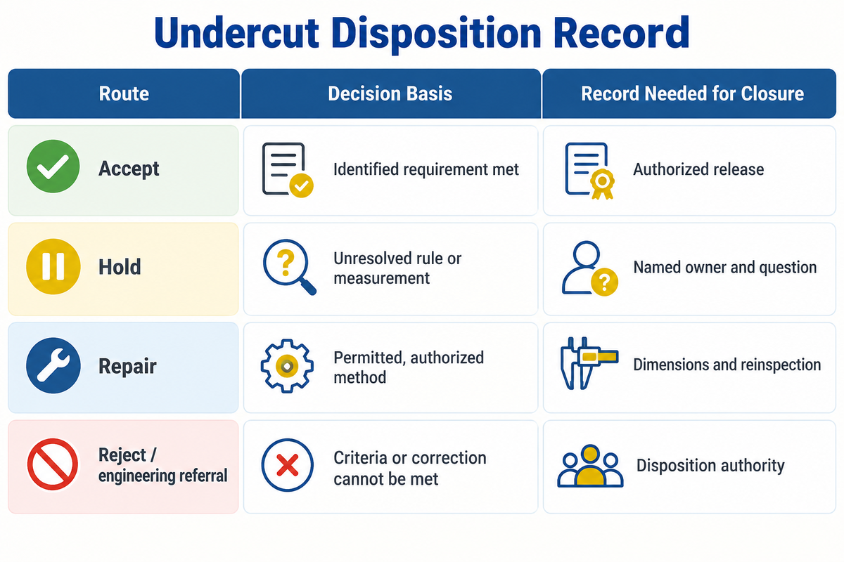
Indications can be accepted only if they satisfy the applicable requirements and release conditions. Hold the member if information or reliable measurement is lacking. Repair using an authorized method if correction is allowed, then inspect again. Reject or refer for engineering disposition if acceptance or authorized repair can’t be accomplished.
The American Welding Society’s 2025 bridge-code explanation describes a preference for blending within specified conditions, with controls on remaining section and the resulting depression. Excessive removal can turn a local groove into a wider section-loss problem. Repair by welding applies where the relevant limits require it; an extra weld pass isn’t an unconditional cure.
“Grinding shall result in a smooth surface.”
Undercut Disposition Record
| Route | Required basis | Close the record with |
|---|---|---|
| Accept | Measured indication meets the identified requirement | Clause/category, observations and authorized release |
| Hold | Missing rule, uncertain access, inconsistent or near-limit reading | Named owner and the specific unresolved question |
| Repair | Permitted, authorized blending or welding procedure | Before/after dimensions and required reinspection |
| Reject / engineering referral | Criteria or approved correction cannot be met | Disposition authority and material routing |
The example member B-17 is being held while its rule and measurement conditions are resolved. If blending is allowed, record the weld size and the remaining parent metal thickness and transition. If welding repair is allowed, address specified controls for the consumables and thermal constraints. The integrity of the joint should be tracked using the inspection plan rather than by the appearance of the surface.
For a 35 mm repair extent, the completion record should identify both the original 0.45 mm observation and the final examined region. Reinspection coverage may extend beyond that original segment under the repair plan. Completing a repair resolves a specific nonconformance and addressing the cause may prevent the next nonconformance.
What evidence should a buyer request before approving repairs?

The repair package should be requested which connects the original observations to the governed requirements, the authorized method, dimensions and final inspection. Agree who approves each stage before work begins. Procurement needs a defined repair scope; quality staff need traceable observations; production needs a clear route back to released output rather than repeated cosmetic rework.
An owner compares two repair quotations for a batch of beam members. The first quotation includes grinding labor. The second includes mapping of locations, an authorized method, dimensional checks, and final inspection. The lower first cost quotation isn’t necessarily a lower price for the same result. Staff needs the before and after conditions, and production needs to know when a member can return to the released queue. The procurement staff separates the labor activity from the deliverables that they hand over and asks each bidder to price the same scope. That comparison would help in identifying omitted inspection or access work without guessing the repair industry rate.
The package below describes the scope of work before any of the contractors touches a weld.
- Member/weld identifiers, mapped extent, raw measurements and instrument record.
- Applicable code, edition, project category and acceptance clause.
- Authorized repair procedure, responsibility and hold points.
- Required final member dimensions and weld profile.
- Specified examination method, coverage, reports and release signature.
Useful distinctions may be found in a 2005 FHWA-hosted investigation of the Oakland Bay Bridge. Prior to the final inspection, work had stopped, and the inspection hadn’t been completed. Subsequent documented completion and testing found no unacceptable flaws in the samples tested. Process marks, and what appears to be a finished weld, indicate a different answer to the question than completion of final inspection. The precedents set by past projects don’t provide general repair criteria.
The 35 mm example should be consistent in the repair scope, location sketches and examination reports. If the reports, examination sketches and location sketches describe different conditions, the buyer, in effect, has an unresolved handover issue even before they discuss price. Quote comparisons become useful when production, inspection and release refer to the same weld.
Prevent repeat undercut on an H-beam welding line
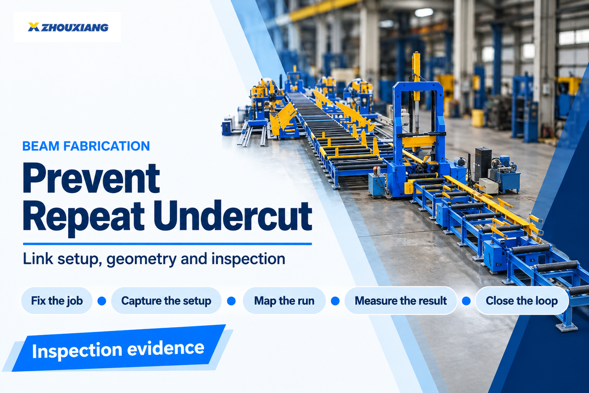
Prevent recurrences of undercut by diagnosing fit-up, actual welding conditions, and toe measurements during a representative production run. Determine where the indications begin and if they correspond to a change in setup or geometry. A line purchase should address acceptable output and inspection access alongside nominal travel speed, because rework consumes capacity after the arc stops.
Zhouxiang supplies H-beam equipment for assembly, submerged arc welding, turning and straightening. For a more thorough background, see our welding and cutting equipment background. In a beam application, the relevant discussion begins with the geometry of the members, the type of joints used, and the inspection requirements.
Beam Run-Off Evidence Sheet
- Fix the job: record drawing revision, material, flange/web dimensions, joint preparation and required weld size.
- Capture the setup: identify the procedure, consumables, electrode position and actual operating conditions.
- Map the run: distinguish starts/stops, steady welding and geometry changes; retain both toes where applicable.
- Measure the result: link profile observations and dimensional readings to member/weld identifiers.
- Close the loop: record any adjustment, affected production and final inspection/release before comparing usable output.
To prevent undercut in welding, select the specified electrode for the material and procedure, maintain suitable filler deposition and control the arc at the joint edges. “Proper welding” shouldn’t be relied upon to replace the settings recorded. Improper welding adjustments can substitute undercut with excess reinforcement, weld discontinuities, or other errors.
Industry Outlook: inspection and standard updates
For projects specified after the 2025 D1.5 changes, capture the contract edition in an inspection handover before reusing an older procedure’s acceptance notes. This affects bridge welding; the shape of an H-beam doesn’t determine that code. Equipment trials should capture the rule and result chosen so that a later inspection team can decipher the record.
Another measurement alternative is digital surface inspection. Hultgren and Barsoum’s 2026 digital visual inspection study looks at the assessment of laser scanned geometry and fatigue. A buyer considering such a system should define its measurement range, access and validation for the intended joint; that research is separate from the capability of any particular production line.
A run-off that shows the example interval of 1240-1275 mm allows quality staff to compare a recorded 0.45 mm observation to the approved setup and any subsequent change. This allows production to distinguish a local repair from a repetitive defect and procurement to evaluate inspection-ready output instead of speed figures alone.
Bring your member drawing, material, weld-size requirements and inspection plan to the discussion of an H-beam welding line. Define the representative run and the records needed for handover before settling the equipment configuration.
Frequently asked questions
Does undercut weaken a weld?
Undercut can weaken a joint by removing parent metal and introducing a notch.
How the effect is assessed
Undercut can weaken the joint through local section loss and stress concentration. Its significance depends on the groove geometry, remaining section, loading and applicable acceptance requirements. A visible groove is a reason to inspect and measure the joint; appearance alone can’t establish acceptability or predict remaining fatigue life. The depth and affected length belong in that assessment.
How can I fix an undercut weld?
Use authorized blending or welding repair route when correction is required.
Repair sequence and controls
First document the indication and compare it with the specified acceptance requirements. If repair is required, obtain the authorized method before removing material or adding weld metal. Controlled blending or a welding repair may be permitted in the particular application, but required dimensions, procedure restrictions and repeat inspection still apply. Correct the production cause separately.
What is underfill in welding?
An underfill is weld fill that leaves the required surface profile low.
Distinguishing the low surface
Underfill is a weld surface that lies below the required adjacent surface because the joint hasn’t been sufficiently filled. Undercut instead describes a groove melted into the parent metal at the weld boundary. Both can occur on one joint, so classify each observed feature and measure it against the applicable requirement rather than judging the bead as a whole.
What does spatter tell me about my welding?
Spatter prompts a process-stability check, but doesn’t diagnose undercut by itself.
Inspecting the exposed profile
Clean away obscuring spatter under the inspection method. Then examine the toe and process conditions; shielding gas checks apply to the relevant gas-shielded process.
After welding, when are welds ground?
Grinding is only permitted by the specified fabrication requirements or authorized disposition.
Preserving dimensions and inspection evidence
Establish the original condition before changing the profile, and follow the specified sequence for cooling, examination and repair. A smooth surface isn’t sufficient evidence of restored dimensions or internal fusion. After authorized blending, verify the remaining parent-metal thickness, required weld size and transition profile, then perform the inspection required by the repair plan before release. Don’t grind merely to hide an indication.
Can a photograph replace an undercut depth measurement?
No. A photograph shows location and appears to show size. It doesn’t indicate the depth of the groove.
What to save with the image
Save the image with a scale, weld identifier and location reference. Retain the dimensional reading and its reference surface in the same inspection record.
References & Sources
This handbook explains inspection and purchasing decisions. Example B-17/W-04 is a worked example, not a Zhouxiang test. The requirements of the specified project and the designated authority of disposition control fabrication acceptance and repairs.
- TWI: geometric shape imperfections, Part 1.
- Portland Community College: Weld Quality, Matt Scott.
- NIST: quantifying uncertainties from a gauge study.
- ISO 5817:2023: public abstract and scope.
- AWS Welding Digest: D1.5:2025 undercut changes, Ronnie Medlock.
- [Niraula and Remes, 2025: severity of local undercut and fatigue life.]
- FHWA: dye penetrant testing, applications and limitations.
- FHWA-hosted Mayes Testing Engineers investigation, May 3, 2005.
- Hultgren and Barsoum, 2026: digital visual inspection.
- The Fabricator: Paul Cameron on welding vocabulary.
- The Fabricator: Tony Anderson on weld discontinuities.


![Robot Welding Parameters [Traceable Window]](https://zhouxianggroup.com/wp-content/uploads/2026/10/robot-welding-parameters-blog-featured.png)


