![Robot Welding Parameters [Traceable Window]](https://zhouxianggroup.com/wp-content/uploads/2026/10/robot-welding-parameters-blog-featured.png)
Robot welding parameters are in a usable process window when an approved combination of settings produces acceptable joints over the range of part variation produced in the fabrication process. A good example of a joint bead is just the beginning. The objective is to capture the welding procedure, robot programme, measured process values and inspection outcomes in such a way that the next person on the shift can reproduce the same joint condition.
Robot welding parameters control the arc, wire delivery, torch movement and joint conditions. Release a process window against the applicable procedure and inspection plan, then connect each weld to its programme revision and measured data.
- Process scope: robotic gas metal arc welding, including MIG/MAG where applicable.
- Electrical and motion units: current in A, voltage in V, torch travel in mm/s or mm/min, wire feed in m/min.
- Release basis: an applicable welding procedure, identified trials and accepted inspection results.
- Traceability: part and weld identifiers joined to programme, schedule, measurements and disposition.
- A faster cycle can produce fewer first-pass good parts per hour.
- Commanded voltage and measured arc voltage can differ.
- Procedure qualification, cell acceptance and weld inspection need separate records.
- A change in fit-up, torch geometry or thermal history can matter even when the displayed settings stay unchanged.
Which Robot Welding Parameters Must Be Controlled?
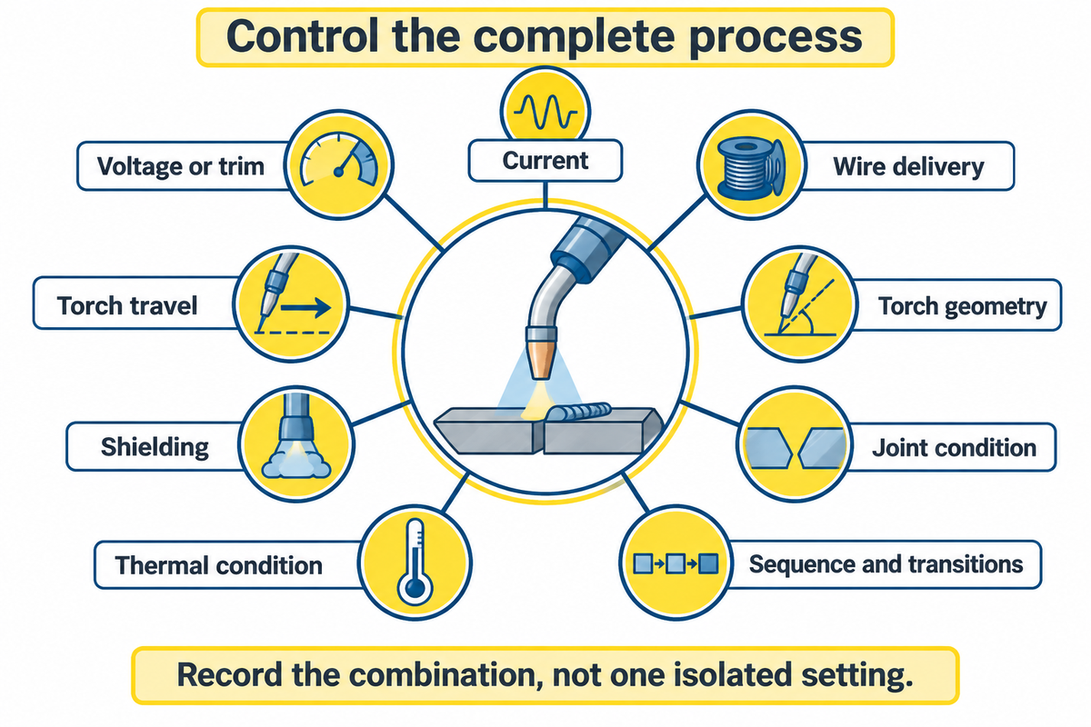
Control the electrical schedule, wire delivery, torch travel and geometry, shielding, material and joint condition as one combination. For robotic MIG welding, include the selected transfer mode and any synergic or pulse programme. For multipass work, add preheat, interpass temperature and the weld sequence, because thermal conditions can change between passes.
TWI’s guidance on measuring arc-welding parameters points to current, arc voltage and travel speed, with other process indicators such as wire feed, gas flow and temperature. The essential question becomes, what variable is commanded, what’s measured, and what’s the physical condition that’s giving the number meaning?
| Family | Record and units | Control question |
|---|---|---|
| Current | Command or feedback, A | Is current independently selected or coupled to wire feed and mode? |
| Voltage or trim | V or the controller’s trim scale | What does the displayed control change? |
| Wire delivery | Wire identity, diameter in mm, feed in m/min | Is delivery consistent with the approved schedule? |
| Travel | Weld-path speed in mm/s or mm/min | Is the value for the welding segment or general robot motion? |
| Welding torch geometry | Tool centre point, angles and working distance | Does the wire meet the intended joint location? |
| Shielding | Gas identity and measured flow in L/min | Is the required shielding reaching the welding zone? |
| Joint and fixture/jig | Drawing revision, measured fit-up in mm | Does production remain inside the validated joint conditions? |
| Thermal state | Preheat and interpass temperature in °C | Is the next pass starting within the procedure’s limits? |
| Sequence and transitions | Pass order, arc start/end and timing in s | Are starts, craters and between-pass conditions controlled? |
Are All MIG Welding Robots The Same?
MIG welding robots can use different power sources, control interfaces, torches, wire feeders, positioners and monitoring options. A robotic welding system couples these components through documented controls. Therefore, when copying a schedule to another welding system, verify the meanings of the controls used and qualify or validate the intended application.
Selecting the right welding methods starts with the required joint, rather than the brand of robot arm. The use of robotic welding uses a repeatable motion system. It still requires compatible tooling and a controlled workpiece. Different weld locations can need different access, orientation and start/end conditions even on the same part.
It’s worth mentioning that stick and MIG welding controls aren’t the same, and a background manual welding teaching list is useful, while a production schedule identifies the process that’s being carried out. Laser welding, TIG welding and spot welding require their own process controls and validation.
Thermal history is also part of this. In a 2021 study of a multipass weldolet-header joint, Mai and colleagues examined how interlayer temperature and welding sequence changed temperature and residual-stress distributions. Their joint-specific study illustrates why an electrical-only record can miss a process condition.
How Do Current, Voltage and Travel Speed Interact?
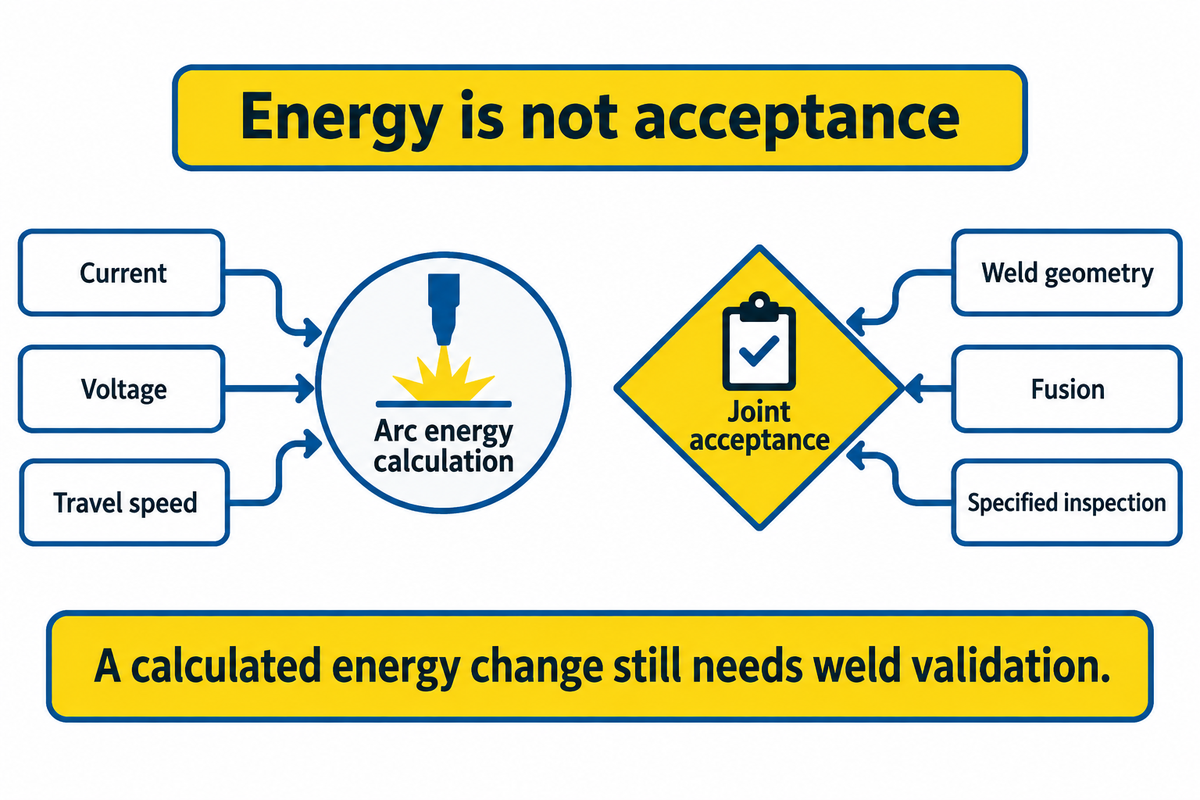
Energy delivered along a weld is a function of current, voltage and travel speed. Wire feed and transfer mode, along with torch geometry, affect arc behavior and deposit. Measured values and a consistent unit of measure are required when comparing trials, especially if averaged signals are reported.
Wire feed influences amperage in common constant-voltage MIG setups; the exact relationship is defined by the selected wire, stick-out and welding power source mode. The effect of voltage is in welding arc behavior and bead geometry. Travel speed affects how the arc and the deposited metal are distributed along the workpiece. A setting chosen for one joint can’t be transplanted to another on the basis of thickness alone.
Optimizing welding parameters means settling on a repeatable, accepted condition, as opposed to attempting to achieve the highest individual setting. Record parameters like travel speed alongside the joint, and transfer mode. Modern welding controls may allow coupled commands, meaning the current welding schedule has to maintain the meaning of the commands in the trial as compared to production.
Example: assume steady DC at 24 V and 200 A, with travel at 8 mm/s. Electrical power is 24 × 200 = 4,800 W. Arc energy per length is 4,800 ÷ 8 = 600 J/mm, or 0.6 kJ/mm. The same travel speed is 480 mm/min; using that unit requires the matching seconds-to-minutes conversion.
Those assumed inputs teach arithmetic. Production settings come from the approved procedure and its validation. TWI distinguishes arc energy and efficiency-adjusted heat input; code terminology and efficiency conventions must remain consistent within the record.
For pulsed welding, averaging voltage and current separately may lose their time relationship. In these cases, use the documented energy method that accounts for waveform. Some instruments described by TWI record waveforms and calculate energy from instantaneous voltage and current values. A one-second average and a high-rate waveform answer different measurement questions. The export method must be congruent with the desired analysis.
“Sometimes, reducing the travel speed will reduce scrap and bad parts”
For the 24 V, 200 A example, increasing travel from 8 mm/s to 10 mm/s reduces the calculated arc energy from 0.6 kJ/mm to 0.48 kJ/mm. That calculation predicts an energy change, not an accepted joint. Weld geometry, fusion and the specified inspection determine if the revised schedule can be released.
Build and Validate a Robot Welding Process Window
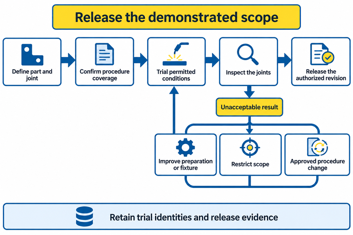
Build a robot welding process window around the defined part, joint and applicable welding procedure, and evaluate the controlled conditions anticipated in production. Release the combination of settings and physical conditions which meets the mutually agreed acceptance criteria. Retain the identities of trials and the authority for any changes.
How are robot welding parameters determined?
Establish robot welding parameters from the documented trials, configured equipment and required procedure, materials and joints. Work within the scope permitted in the procedure, evaluate representative fit-up and thermal conditions, and inspect the resulting joints. The acceptable programme must link to the specific schedule and trial evidence used for release.
Separate procedure qualification from a machine demonstration. ISO 15614-1:2017’s public abstract describes procedure testing for its defined steel and nickel applications and the associated range of qualification. It distinguishes levels 1 and 2, with greater testing and narrower ranges for level 2. Where that standard applies and neither the contract nor application standard names a level, its abstract specifies level 2.
Existing qualification routes also matter. ISO 15612:2018 addresses adoption of a standard welding procedure specification based on tests performed by another organization, under defined conditions. A new robot purchase does not automatically require the same qualification route for every job. The welding authority must identify the applicable route and coverage before production release.
Consider a fabricated bracket that passes a trial with closely fitted parts. Normal incoming parts, however, may vary at the joint. Engineering records the drawing’s permitted fit-up conditions, chooses trial conditions within the applicable procedure and links each test piece to its measured geometry. Quality, then, applies the agreed inspection plan. If one permitted production condition produces unacceptable joints, the team can improve part preparation or fixturing, restrict the released scope, or develop an approved procedure change. In this case, Purchasing would be able to ascertain a defined production capability, rather than taking a demonstration based on unusual and/or favorable parts. The record also gives the next shift the fixture and programme revisions that gave the accepted result.
Process Window Release Record
| Release field | Evidence to retain | Decision owner |
|---|---|---|
| Part and joint | Drawing, weld location and revision | Design/welding engineering |
| Procedure scope | Applicable specification, qualification route and coverage | Responsible welding authority |
| Materials | Base material, filler and required batch identities | Engineering/quality |
| Configured equipment | Power source, mode, torch, feeder and positioner | Integrator/engineering |
| Electrical schedule | Approved commands, ranges, units and schedule revision | Welding engineering |
| Robot geometry | Programme revision, tool/work coordinates and fixture | Robot programming |
| Production variation | Measured fit-up, orientation and thermal conditions | Engineering/production |
| Trial identity | Test piece, weld/pass ID and timestamped process record | Trial team |
| Inspection | Specified method, extent, criteria, results and disposition | Quality |
| Release and change | Authorized version, operating scope and review triggers | Engineering/quality |
Maintain the trial count, test methods and acceptance limits associated with the applicable qualification and inspection plan. An arbitrary percentage band around a nominal setting can’t replace that plan. A change in joint type, mode or released material scope needs a coverage review before the old record is reused.
When implementing robotic welding, the preceding manufacturing processes are included in the trial boundary. Cutting and forming, together with fit-up, present the joint to the cell. A robotic welding machine in mixed-product manufacturing environments needs a release record for its intended part family, with changeover conditions stated explicitly.
Trace Each Weld to Its Programme and Actual Process Data
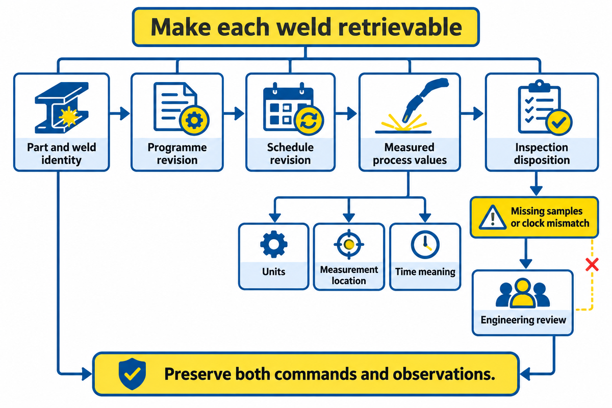
A weld record joins the part and weld identity to the programme revision, schedule revision, measured process values, and inspection disposition. Store units, measurement location and time meaning alongside each channel. A retrievable record should allow quality to identify the affected work, and allow engineering to reconstruct the released condition.
Data semantics are engineering constructs. William G. Rippey’s 2004 NIST Welding Data Dictionary spans weldment design, fabrication and inspection. More recently, Magyar and colleagues’ 2024 research-cell study includes the acquisition of electrical, wire-feed, motion and arc-state data. Both describe the practical integration of field data: fields must preserve meaning across systems.
Setpoint-to-Actual Traceability Map
| Record layer | Required meaning | Retrieval check |
|---|---|---|
| Part identity | Unique part or controlled batch reference | Locate affected production |
| Weld/pass identity | Drawing location and pass sequence | Separate adjacent welds |
| Programme version | Released robot path and coordinate configuration | Recover the executed motion |
| Schedule version | Power-source mode and commanded values | Recover the approved commands |
| Actual electrical values | A and V, measurement point and aggregation | Distinguish arc measurement from terminal display |
| Wire/motion feedback | m/min and mm/s, measured or commanded status | Convert units before comparison |
| Time and event | Timebase, arc state, starts/stops and alarms | Join events to the right weld |
| Thermal condition | Applicable temperature in °C and pass context | Recover interpass history |
| Measurement status | Instrument identity and verification/calibration evidence | Judge fitness for the measurement |
| Inspection disposition | Method, result, acceptance decision and authority | Separate logged from accepted work |
How do you program a robotic welder?
Programme the robot’s weld path and coordinated equipment sequence to bind released motion to the approved welding schedule. A teach pendant or offline programming package defines motion and events; commissioning must establish the correct tool and work coordinates, arc transitions and controlled operating method before welding trials support production release.
The programming language and interface determine how instructions are expressed, while the released job tells the robot to execute a particular path and event sequence. Equipment integrated with the robot needs corresponding configuration records. A successful simulation establishes a planning result; physical welding operations still need the cell’s authorized commissioning and trial process.
Example: Quality finds a suspect weld after a shift change. The part identifier retrieves a weld record, but its schedule name was reused after editing. Data for current and voltage by themselves aren’t sufficient to reconstruct the previous commands. Versioned programmes and schedules resolve this ambiguity: the investigator aligns the affected weld to the corresponding revisions, and reviews measurements, events and inspections. The same check should expose missing samples and a clock mismatch rather than silently substitute nominal values. Agree on the response to incomplete records before production, including affected-part holds and an engineering review. A successful retrieval test is worth more than a dashboard screen capture.
Units deserve a deliberate check: 6 m/min is 100 mm/s for wire movement, while 8 mm/s is 480 mm/min for torch travel. Those example quantities describe different movements. A shared “speed” column without units or channel identity can hide a large integration error.
Diagnose Process Drift Before Changing the Weld Schedule
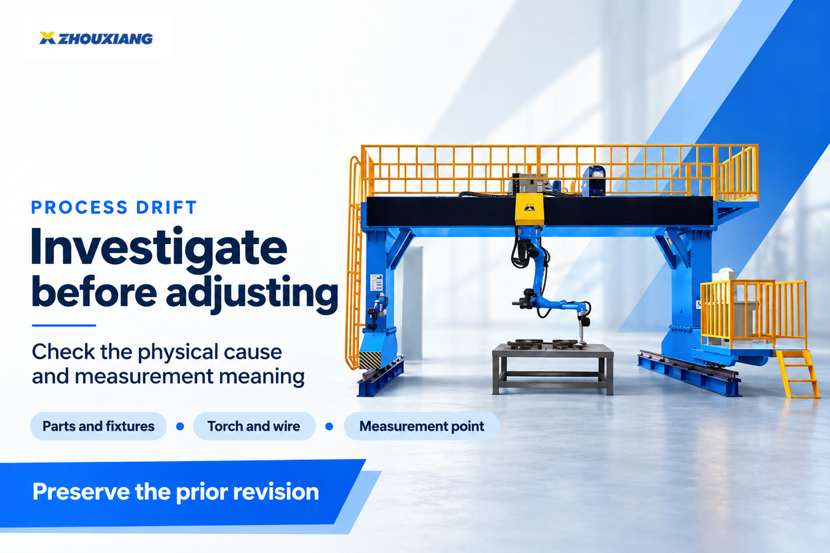
Review the recent changes to parts, tooling, consumables, wire delivery, and shielding before approving a revised weld schedule. First verify that the programme and measurements are as they should be. Then separate physical process changes from a deliberate parameter change, with maintenance and testing performed by authorized personnel under the cell’s safety procedures.
A changed contact tip, sometimes called a weld tip, or a torch collision can affect wire position and tool geometry. A change in the position of a part can also result in an off-location condition. Rather than assuming that an increase in current or a reduction in speed is required, you should investigate the above possibilities. TWI’s measurement guidance also explains why changing the voltage measurement point can create an apparent difference.
| Observed change | Investigation record | Release decision |
|---|---|---|
| Weld moves off location | Fixture/part condition, tool check and recent collision or tip change | Restore and verify geometry before reviewing schedule changes |
| Unstable wire delivery | Feeder, liner, consumable and delivery history | Resolve delivery faults through approved maintenance |
| New porosity indication | Gas delivery, material condition and inspection context | Identify the cause and disposition affected work |
| Voltage trend shifts | Same channel, measurement point, timebase and mode | Separate measurement changes from process drift |
| Crater or start problem | Arc transitions, schedule revision and timing | Review the approved start/end sequence |
| Multipass result changes | Pass order and preheat/interpass record | Review thermal conditions and qualification coverage |
How to adjust a robotic welder?
After identifying the cause of the problem, adjust a robotic welder through an authorized change to the documented schedule, preserving the previous programme and settings and recording the changed variable. Perform the required inspection and testing and release the revised programme only after the specified acceptance and qualification requirements have been satisfied.
ISO 17662:2025 addresses calibration, verification and validation of equipment used for welding and process-variable control. Include measurement fitness in the investigation. Repeatedly correcting a schedule to compensate for a worn or displaced component can make the next replacement behave differently again.
Accept a Welding Robot System on Production Evidence
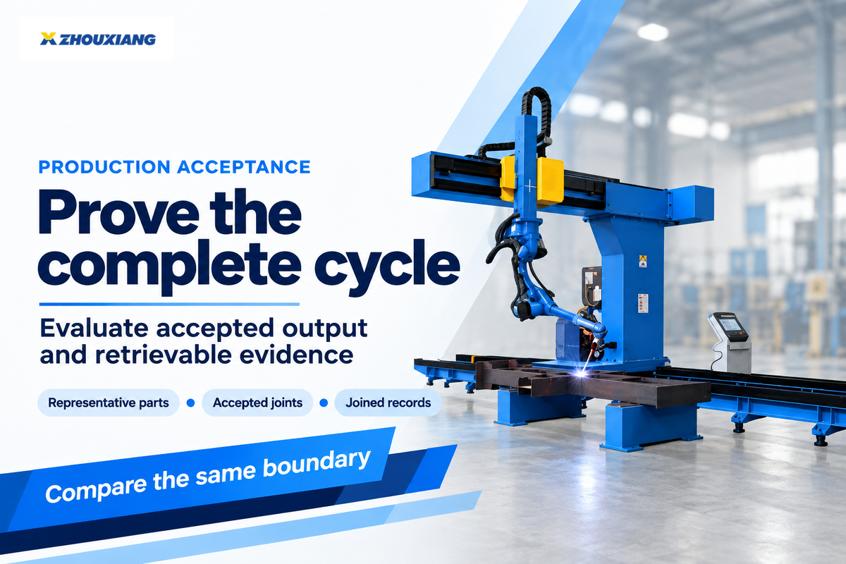
Accept a welding robot system against the agreed part mix, complete cycle boundary, weld acceptance criteria and demonstrated data retrieval. The trial should exercise the configured cell and expected production conditions. Keep procedure qualification, personnel competence, measurement verification, and product inspection identifiable within the acceptance package.
ISO 17635:2025 links selection and evaluation of weld non-destructive testing to quality requirements, material, thickness, process and testing extent. Specify the inspection method and acceptance levels and do not convert a weld quality grade directly to an NDT acceptance level.
- Define the trial. Agree representative drawings, materials, joints, fit-up conditions, fixtures and the applicable procedure.
- Witness the complete cycle. Include loading, positioning, welding, unloading and the stated inspection boundary.
- Retrieve the evidence. Request the programme/schedule revisions, measurement status, an actual export and joined inspection dispositions.
- Close the exceptions. Record rejected work, interruptions, missing data, recovery method and authorized production scope.
For a Zhouxiang request, bring that trial package when comparing welding robot systems. The part drawing and acceptance requirement should drive the equipment discussion, including the power source, fixture, positioner and data interface required in the quoted configuration.
Example: assume a cell-time cost of $60/h and compare two uninterrupted one-hour trials. A 60 second complete cycle starts 60 parts/h; at 95% first-pass yield, it produces 57 first-pass good parts/h. A 50 second cycle starts 72 parts/h, but at 75% first-pass yield produces only 54 first-pass good parts/h. Cell-time cost is therefore $60 ÷ 57 = $1.05 per good part versus $60 ÷ 54 = $1.11. Rework recovery is excluded, as are material, wire, gas and scrap costs. The exercise isolates cell-time contribution; a purchasing comparison must add the remaining costs on the same basis.
| Measure | Trial A | Trial B |
|---|---|---|
| Complete cycle | 60 s/part | 50 s/part |
| Starts per hour | 60 parts/h | 72 parts/h |
| First-pass yield | 95% | 75% |
| First-pass good output | 57 parts/h | 54 parts/h |
| Assumed cell-time rate | $60/h | $60/h |
| Cell-time cost per first-pass good part | $1.05/part | $1.11/part |
Hidden bottleneck map
Loading and fit-up constrain starts; torch cleaning and maintenance interrupt availability; inspection queues delay accepted output; missing record joins delay disposition. Measure where the lost time occurs before purchasing a faster robot. Labor savings and maximum productivity projections should use the same part mix, staffing boundary, and cost definition.
Increased productivity requires the rest of the line to handle the accepted output. Modern manufacturing projects should therefore compare the bottleneck before and after automation, including inspection and material movement. An optimal performance target for arc-on time can be a poor investment target when rejected work consumes the saved time.
In the assumed comparison, shortening the cycle from 60 s to 50 s lowers first-pass good output from 57 to 54 parts/h. Compare accepted output and complete cost boundaries before approving a speed-focused investment.
Where Welding Monitoring and Adaptive Control Are Heading

Choose the functions of monitoring and adaptive control for a defined decision about production: determine a process change, correct variations within acceptable limits or retrieve a weld record. Each function needs a demonstrated operating scope and an agreed exception response. For current projects, measurement, personnel and inspection requirements deserve the same attention as a controller’s new features.
The 2025 editions of ISO 14732, ISO 17662 and ISO 17635 address different parts of that system: personnel qualification, welding-equipment measurement assurance and weld testing. ISO 14732:2025 concerns operators and weld setters involved in mechanized and automatic welding within its scope. Procurement should separate training, qualification and the authority to alter a production programme.
The AWS D16 committee’s published-document list includes robotic arc-welding safety and risk-assessment documents dated 2026, alongside its 2025 personnel-qualification specification. So safety and integration reviews are in the project plan for both industrial robots and collaborative robots. Calling a unit a cobot doesn’t eliminate the risks associated with welding, and an appropriate risk assessment is still required.
Monitoring also has a measurable detection boundary. In their 2025 GMAW acoustic-monitoring paper’s abstract, Cullen and Ji report detecting 27 of 30 burn-through occurrences and all 22 porosity defects in their study. Estimates of penetration were compared to etched cross-sections. A potential buyer of similar equipment needs information on defect classes, missed events, and evidence of validation.
A pragmatic development path is joining vision systems, process channels and revision records without losing their individual meanings. Geometry sensing can be used for positioning; process monitoring can flag deviations; the agreed inspection defines product disposition. For a new welding automation project, make retrieval, exception handling and permitted adaptive changes part of the acceptance demonstration. An extra sensor is useful when it improves a defined production decision.
The welding industry has several welding technologies, but what counts is the function each performs. Different types of welding require different signals and qualification boundaries. For a buyer wishing to prevent defects, a monitoring alarm should trigger an agreed response and an accepted inspection should close the quality decision.
Frequently Asked Questions
What are the 5 welding parameters?
CLAMS describes five manual stick-welding technique factors.
Current, length of arc, angle, manipulation and speed make up the familiar CLAMS mnemonic. Its context is manual stick welding. A robotic GMAW schedule also needs wire delivery, voltage or trim, transfer mode, shielding, torch geometry and joint conditions. Treat the five-item list as a teaching aid, then build a complete record for the actual welding process and approved application.
What is the typical welding speed of a welding robot?
Use a joint-specific validated travel speed, not robot axis speed.
No single travel speed suits every robot weld. Process mode, material, joint geometry, required weld size, wire delivery and position change the usable value. A robot’s maximum axis speed describes motion capability rather than an accepted welding schedule. Compare suppliers using representative parts, a defined complete cycle and the same weld acceptance criteria, with the executed torch speed recorded in consistent units.
How to test a program in a welding robot?
Use the authorized path-check and welding-trial procedure for the cell.
A competent team checks programme identity, tool and work coordinates, fixture condition and the approved operating method. Path verification and a welding trial have different purposes. For the welding trial, retain part and weld identities, material and consumable details, schedule revisions, measured process values and inspection results. Release the production version through the responsible engineering and quality process while preserving applicable procedure qualifications.
What are the downsides of robotic welding?
Fixtures, programming, maintenance and integration add work.
Repeatable motion still requires controlled parts, reliable wire delivery, trained personnel and accepted inspection. High product variation or frequent changes can increase setup time and weaken the expected productivity benefit.
What factors should be considered when calculating cost and ROI for a robotic welding cell?
Calculate cost per accepted part using one consistent production boundary.
Include equipment, integration, fixtures, programming, loading labor, consumables, inspection, maintenance, downtime, scrap and rework. Separate one-time investment from recurring operating costs, then compare the same part mix and acceptance criteria. Arc-on time alone omits work that can constrain the production line. A reliable comparison records the complete cycle and first-pass good output. Finance can vary utilization and reject-rate assumptions to see how cost-effectiveness changes; production must assess whether the cycle is repeatable, while quality owns the acceptance decision. Record who supplied each input and whether it comes from a quotation, production measurement or planning assumption. When comparing manual welding with automated welding, retain the same cost boundary and staffing assumptions so that an apparent return on investment isn’t created by leaving out different tasks.
Prepare the part, the process and the acceptance package
Bring a representative joint drawing, material and consumable identities, the required weld acceptance criteria and the data fields needed for traceability. Zhouxiang’s equipment discussion can then start with the production task and the evidence required to release it.
For buyers working with Zhouxiang’s welding equipment team, a pragmatic focus is a part-fitting cell and a process record that survives handover. Parameter names, software functions and trial results should remain connected to the quoted configuration.
References & Sources
- Measurement of Arc Welding Parameters, TWI technical guidance.
- Influence of Interlayer Temperature and Welding Sequence on a Weldolet-Header Joint, Mai and colleagues, Materials, 2021; abstract via PubMed.
- What Is the Difference Between Heat Input and Arc Energy?, TWI.
- Robots Support High-Speed Welding, Association for Advancing Automation, May 2000.
- ISO 15614-1:2017, International Organization for Standardization, public abstract.
- ISO 15612:2018, International Organization for Standardization, public abstract.
- A Welding Data Dictionary, William G. Rippey, National Institute of Standards and Technology, NISTIR 7107, 2004.
- Real-time data visualization of welding robot data and preparation for future of digital twin system, Magyar and colleagues, Scientific Reports, 2024; full article via PubMed Central.
- ISO 17662:2025, International Organization for Standardization, public abstract.
- ISO 17635:2025, International Organization for Standardization, public abstract.
- ISO 14732:2025, International Organization for Standardization, public abstract.
- D16 Committee on Robotic and Automatic Welding, American Welding Society, published-document list.
- Online Defect Detection and Penetration Estimation System for Gas Metal Arc Welding, Cullen and Ji, 2025; public abstract.