
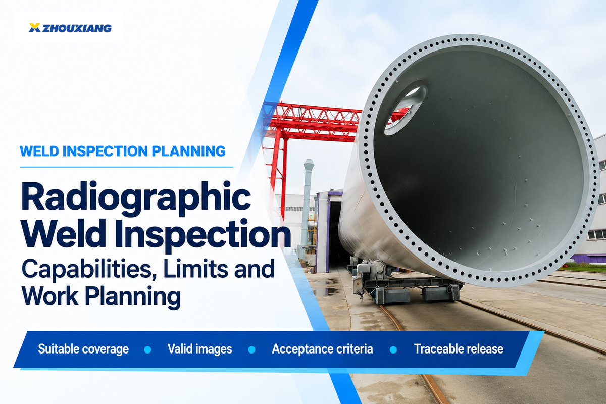
- Method: penetrating radiation produces an image of internal structure.
- Image receptors: film, computed radiography plates or digital detector arrays.
- Main limitation: a projected image can hide or overlap features.
- Purchase-order essentials: examination scope, technique, acceptance basis and traceable records.
A clear weld image can still leave a production manager without permission to release the part. Radiographic weld inspection must integrate a valid technical examination with the appropriate acceptance decision, the correct weld identity and an available production window. That integration can’t be overlooked when a part is waiting on rotators and the next step in fabrication requires a signed result.
Radiographic weld inspection uses X-rays or gamma rays to reveal internal discontinuities in a projected image. Flaw orientation and examination geometry affect detection. Agree the method, coverage, acceptance criteria and records before scheduling work.
- A valid image doesn’t mean every possible flaw is visible.
- Image quality and weld acceptance answer different questions.
- A digital detector changes acquisition and records; ionizing radiation remains.
- Image retakes and weld-repair reinspection need separate scope and charges.
What radiographic weld inspection can show
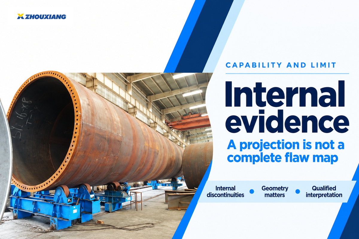
As a non-destructive testing method, radiographic testing describes changes in radiation attenuation through a weld and the surrounding material. A film or detector records the resulting image, which a qualified interpreter assesses for relevant indications. The method allows for the identification of internal discontinuities of the test object without breaking it, and provides a record for future review.
Contrast can be achieved through the presence of certain inclusions and other volumetric features and porosity in a part. A discontinuity can only be rejected after its characteristics are compared with the acceptance standards. That distinction prevents an image annotation from turning into an unauthorized repair instruction.
Industrial radiography uses either machine-generated X-rays from an energized X-ray tube or gamma radiation from an appropriate radioactive source. Gamma radiography makes use of gamma radiation from iridium-192 or cobalt-60, among other radioactive materials described by the U.S. Nuclear Regulatory Commission. Film versus digital is a different consideration. Changing the receptor doesn’t change a gamma source into a switchable X-ray machine. The U.S. Environmental Protection Agency’s industrial radiography guidance explains the distinction of the sources and the need for control of access.
Applications include weld testing in fabrication, pipeline construction and aerospace, and examination of a casting. Similar equipment names don’t mean testing procedures are interchangeable. The shape, type of material, and constraints of the situation still determine the type of examination. X-ray inspection of a small part and inspection of a large tower shell pose different problems in access and handling.
Projection is the main restriction. Features at different depths can overlap in an image, and conventional radiography does not automatically provide a complete three-dimensional flaw map. Projection imaging is different from CT, an option listed in TWI’s radiography overview.
Defects and blind spots: why orientation matters
Flaw shape and orientation affect radiographic visibility. A beam of radiation must produce a detectable attenuation difference through the discontinuity. Volumetric flaws and tight planar flaws present different challenges, and certain flaws may not be detectable by radiographic methods. A satisfactory image-quality result supports the examination technique; it cannot establish equal sensitivity to every flaw shape and direction in the joint.
Munns and Schneider, TWI researchers, studied planar-flaw detection in thick steel welds in their 1999 reliability study. Their analysis involved interacting variables, including flaw gape and orientation. A study of testing of welds in a different configuration shouldn’t set a standard for minimum crack size or a thickness cutoff in a different weld.
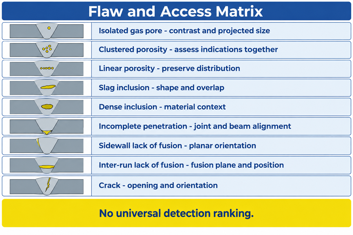
Flaw and Access Matrix
Use this classification matrix to relate a suspected flaw to the corresponding technical concern it raises. Performance of detection can’t be ranked based on the entries.
| Type / family | Image or geometry issue | Planning decision |
|---|---|---|
| Isolated gas pore | Contrast and projected size affect visibility. | Define the applicable indication evaluation. |
| Clustered porosity | Several indications must be evaluated together. | Specify the relevant acceptance rule and assessed area. |
| Linear porosity | Distribution along the weld matters. | Preserve position and orientation in the report. |
| Slag inclusion | Shape, density contrast and overlap affect interpretation. | Relate the indication to weld location and acceptance. |
| Dense inclusion | Image appearance differs from a gas void. | Use the appropriate material and process context. |
| Incomplete penetration | Joint configuration and beam alignment matter. | Review root geometry in the proposed technique. |
| Sidewall lack of fusion | A tight planar feature can be poorly oriented for RT. | Evaluate complementary examination and its approval. |
| Inter-run lack of fusion | The fusion plane and its position alter detectability. | Evaluate the credible flaw mechanism, not appearance alone. |
| Crack | Opening and orientation can make detection difficult. | Use a technique suitable for the expected crack plane. |
Here’s an example of a fabrication review for a butt weld. It’s being checked for porosity, but the history of welding has raised a concern for sidewall fusion. Increasing the number of images without addressing that flaw plane can leave the important question unanswered. The responsible examiner needs both the joint drawing and the suspected mechanism to select coverage or a complementary method.
Decision: A quotation describing only “internal defects” is too broad to capture the detection objective. Identify flaw families and examination volumes in the scope package.
Film, computed radiography and digital detectors
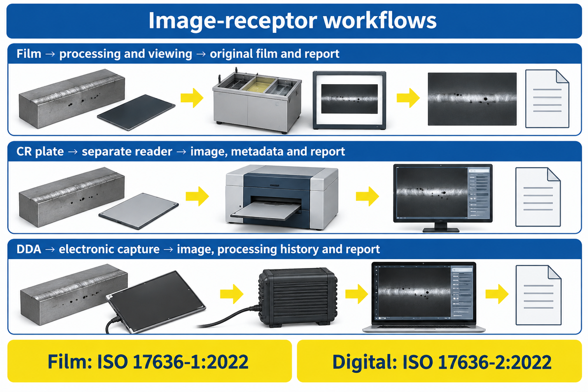
Film radiography, computed radiography and digital detector arrays differ in how an image is captured, processed, and delivered. Each still requires adequate acquisition geometry and image quality. A digital workflow can impact processing and delivery, but the fundamental constraints of the work and the project’s acceptance criteria still apply.
What is the difference between Computed Radiography (CR) and Digital Radiography (DR)?
Computed radiography records an image on a reusable imaging plate that is read by a scanner. Detector-array systems capture image data electronically, generally via a flat panel detector. “Digital radiography” is also an umbrella term, so a purchase order should explicitly name CR or DDA rather than rely on the abbreviation DR.
| Receptor | Processing route | Record to specify |
|---|---|---|
| Radiographic film | Film exposure and processing, followed by viewing. | Original film, identification and report; any scanning arrangement. |
| CR imaging plate | Plate acquisition followed by a separate reader. | Digital image, acquisition metadata and report. |
| Digital detector array | Electronic image capture and associated software processing. | Image data, required metadata, processing history and report. |
The technical split appears in ISO 17636-1:2022 for film techniques and ISO 17636-2:2022 for digital detectors, including CR and DDA. The digital part has a corrected version dated 2023-02.
“Modern advances make RT a method of great importance for continued development of automation and artificial intelligence.”
For a buyer comparing x-ray film with an electronic capture, a fair comparison is a complete deliverable: allowed technique, usable image, interpretation and agreed archive. Faster image availability by itself doesn’t resolve the later decision steps.
When should you use RT instead of UT?
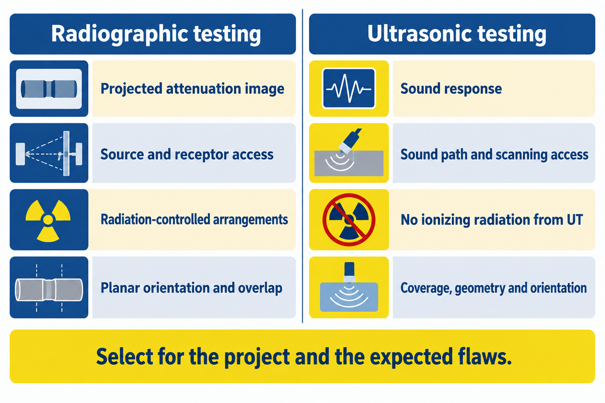
Use RT when the governing requirements permit it and a suitable technique addresses the expected flaws and actual joint geometry. Ultrasonic testing can be a better fit for other flaw orientations or access conditions. Method selection should be in line with the examination objective and coverage demonstrated by the party, rather than a universal preference for RT or ultrasound.
ISO 17635:2025 relates method selection to quality requirements, material, weld thickness, welding process and examination extent. Selecting an NDT method requires those inputs together; a single wall-thickness number cannot replace them. A proposed substitution also needs acceptance under the requirements of the governing project.
- Produces an attenuation-based projected image.
- Requires suitable source and receptor access.
- Needs radiation-controlled work arrangements.
- Must address planar-flaw orientation and overlap.
- Uses sound response and technique-specific interpretation.
- Requires a suitable sound path and scanning access.
- Avoids ionizing radiation from the examination method.
- Must address coverage, geometry and flaw orientation.
In a 2023 Materials study, Herceg and colleagues compared RT and phased-array UT on three welded test plates containing artificial flaws. Both methods detected the defects. However, they differed in their ability to reveal adjacent features. This study supported the need to perform a method-specific comparison. It didn’t prove that RT or phased-array UT always detects more.
Another consideration is surface examination. Depending on the material, penetrant inspection can provide information about surface-breaking discontinuities. Magnetic particle inspection can provide information about discontinuities in suitable ferromagnetic materials. The confirmation of magnetic properties of ferrous alloy doesn’t answer the question of surface examination. These test methods give different information from an internal volumetric examination.
For a joint with restricted receptor access, a suitably demonstrated UT technique may offer a practical route. For a contract requiring a radiographic record, a change in methods requires the authorized project decision prior to the finalization of the quote.
Standards, image quality and weld acceptance
Depending on the agreement, examination validity and the application of acceptance criteria determine whether a weld is acceptable. To authorize a weld, a report should relate the weld to the requirements of the method, the applicable documents, and the individual authorized to make the decision.
ISO 17636-1:2022 and ISO 17636-2:2022 specify their respective radiographic techniques. ISO 10675-1:2021 provides radiographic acceptance levels within its stated steel, nickel, titanium and alloy butt-weld scope. The appropriate material and joint and project specification determine which acceptance levels apply.
ISO 17635:2025 also explains that NDT acceptance levels cannot be directly interpreted from ISO 5817 or ISO 10042 weld quality levels. Writing a quality level on a drawing does not by itself resolve the complete testing and grading of welds.
Is radiographic weld inspection required?
When specific construction requirements or an approved design or a contract require RT for a weld, RT is required. The extent of examination is determined by the requirements of the project and not by the requirement to examine a weld because it can be radiographed. A repair examination or proposed alternative method must follow the corresponding project requirements and authorized disposition.
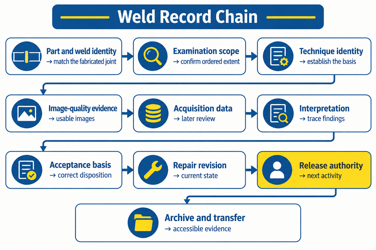
Weld Record Chain
The following handover fields connect examination evidence with a release decision. They’re an editorial record template to be customized for the contract.
| Record field | Required connection | Decision supported |
|---|---|---|
| Part and weld identity | Drawing revision, weld map and durable identification. | Match the result to the fabricated joint. |
| Examination scope | Examined length/area and relevant coverage references. | Determine whether the ordered extent is complete. |
| Technique identity | Applicable procedure and permitted acquisition route. | Establish the examination basis. |
| Image-quality evidence | Required quality assessment linked to the images. | Determine whether the images are usable. |
| Acquisition data | Required original parameters and retained processing information. | Support later technical review. |
| Interpretation | Indication locations and report author. | Trace the reported findings. |
| Acceptance basis | Document edition, applicable clause and project instructions. | Apply the correct disposition rule. |
| Repair revision | Original result, repair location and re-examination result. | Distinguish the current state from superseded results. |
| Release authority | Authorized disposition and any outstanding hold points. | Permit the next production activity. |
| Archive and transfer | Custodian, retention period, file format and receiving-software test. | Keep the evidence accessible over the agreed period. |
Personnel competence belongs in the same purchase order review, with its evidence. ASNT’s explanation of employer-based certification distinguishes third-party certification, employer certification under a written practice and training records. An AWS CWI welding inspector credential, RT method authorization, agency qualification and radiation authorization answer separate questions.
Inspection process and safe work planning
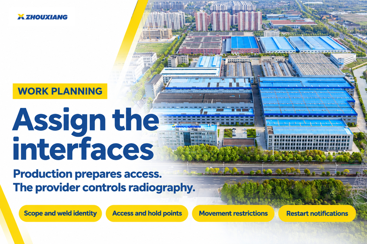
A proper implementation of the inspection process requires identification of a ready weld and a traceable disposition. Production specifies the level of fabrication and access. The examination provider is the owner of the authorized technical and radiation safety arrangements. Interpretation and final release follow in accordance with the responsibilities assigned by the governing requirements and contract.
How is radiographic testing done?
From a work-planning perspective, the execution of radiographic testing proceeds through scope definition, identification and readiness of a weld, approved image acquisition, interpretation and report. The examination provider selects and implements the examination technique with the necessary controls. Production manages access and hold points. A designated authority resolves the resultant action prior to the commencement of the next restricted activity.
An illustrative shop handover shows why identity matters: a contractor receives a shell ready for inspection, but its drawing revision and weld map disagree. Acquiring the image could potentially create a record that can’t be traced to the required joint. In such an instance, resolve the discrepancy in identity, prior to examination and don’t attempt to correct the documentation after the shell has been moved.
Gene Mathers’ TWI radiography discussion relates weld identification to image quality and interpretation. Reliable non-destructive testing needs that connection throughout the work package, including any repair revision.
Radiation safety determines when and where adjacent operations may proceed. The examination provider’s authorized specialists establish and control the work arrangements. Welding screens, and/or ordinary protective clothing, and a production supervisor’s presence don’t create a safe radiography area. The EPA guidance explains that the members of the public must remain outside the controlled testing area.
For production coordination, assign ownership of the inspection window, access readiness, movement restrictions, and restart notifications. Keep these interfaces separate from instructions for source handling or exposure. A later shift may be useful only if the responsible provider is able to implement the required safety considerations and site controls.
Workload, turnaround and quote inputs
Comparable inspection quotations require the same examination package and same definition of completion. A per-weld price may hide different coverage, image-processing charges, or reporting obligations. Separate technical scope from site availability. Price image retakes and weld repair re-inspection as distinct events.
Seven-Input Quote Sheet
Copy these fields into one request for quotation sent to each provider of radiographic inspection services. ASTM E1742/E1742M-23 identifies contract-agreement subjects including qualification, examination coverage, responsibility and records; the seven-row grouping below is a purchasing aid.
| Input | What to include and confirm |
|---|---|
| Geometry and material | Drawing revision, weld type, material, thickness and dimensions; weld map and quantity. |
| Examination extent and pricing unit | Specified length/area, coverage basis and technique route; price per image, weld, length, shift or defined lot. |
| Requirements and responsibility | Document editions, acceptance clauses, personnel and agency qualifications, engineering approval and final disposition owner. |
| Access and readiness | Source/receptor access, support and handling interfaces, surface condition, site restrictions and responsibility for delays. |
| Work and release windows | Available slots, mobilization, acquisition, interpretation, reporting and any customer review deadline. |
| Record package | Required original data, report, repair links, receiving-software readability, custody and retention duration. |
| Retake and repair terms | Separate charges and responsibility for unusable images, weld repairs, re-examination, remobilization and revised reports. |
For a testing laboratory or mobile contractor, verify the named examination scope and the authorization separately from general quality assurance certification. Request a sample record package and agree on the route to resolve a disputed indication. Obtain quotes for identical testing services and compare the totals.
Release Queue Model
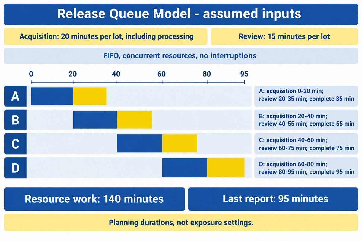
Assumed inputs: four inspection lots are available at time 0. One acquisition resource needs 20 minutes per lot, including its assumed processing work. A separate reviewer needs 15 minutes per lot, starting only after that lot’s images are available. Both resources are assumed to be FIFO, work concurrently and have no interruptions. Report completion is the endpoint. These are planned durations and not exposure settings.
| Lot | Acquisition window | Review window | Report complete |
|---|---|---|---|
| A | 0–20 min | 20–35 min | 35 min |
| B | 20–40 min | 40–55 min | 55 min |
| C | 40–60 min | 60–75 min | 75 min |
| D | 60–80 min | 80–95 min | 95 min |
Review of each lot begins at the later of the acquisition finish of that lot or the previous review finish. The total resource work is 4 x (20 + 15) = 140 minutes, but the reports are completed in 95 minutes by the concurrent work of the two resources. If the same person performs both stages sequentially, the stated overlap disappears and the total becomes 140 minutes under these assumptions.
An additional customer-signoff wait extends release beyond report completion. An image retake sends work back through acquisition and review; a weld repair adds the repair activity and the required re-examination before disposition. No repair duration or defect rate is assumed here. Budget the responsible resource and queue for each branch rather than burying both in one “rework” allowance.
In this four-lot example, 80 minutes of acquisition overlaps with 60 minutes of review, producing the last report at minute 95. Cutting image acquisition alone changes only part of that schedule. The same lot identities must remain with the images, report and any later approval to release the product.
Wind tower production: plan support and access
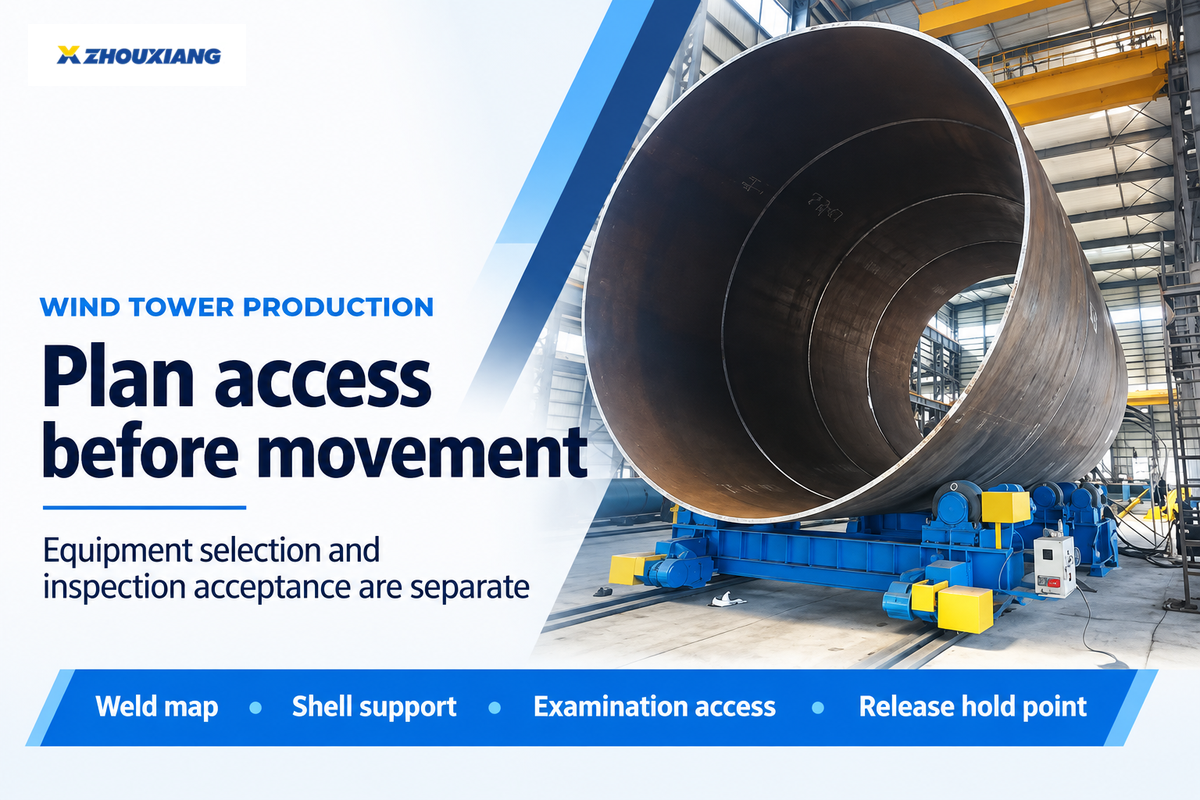
Inspection planning must integrate the weld map, shell support, access and production hold points. Longitudinal and circumferential seams present different handling interfaces. The equipment arrangement must allow the required examination to be conducted without losing weld identity, while movement and subsequent operations follow the release conditions of the project.
Zhouxiang’s wind tower production line integrates plate preparation and forming, welding, handling and inspection interfaces. Define the equipment sequence and the inspection package; each has a clear owner for the deliverables in the quote.
An illustrative tower-shell review has a circumferential seam accessible at one station but obstructed after the next assembly step. The inspection hold point is placed at the station where access is available. A blanket thickness rule doesn’t determine the obstruction. The drawing and qualified technique determine whether the planned method is applicable.
Welding rotators are part of the discussion on support and movement. Their fabrication role does not determine radiation controls or the validity of an examination. The provider and equipment team need a shared layout showing the shell, support positions and required access before an inspection window becomes a credible schedule commitment.
The same planning approach applies to hydraulic fit-up rotator arrangements. Alignment and examination interfaces should be addressed as part of the fabrication role. Hardware selection and inspection acceptance remain distinct engineering decisions.
Industry outlook: digital records and evolving standards
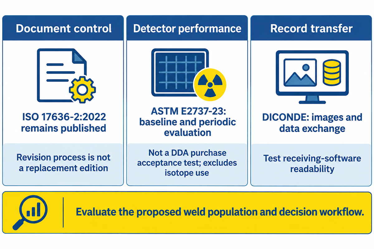
Digital-radiography purchasing should distinguish between the performance of the acquisition system and record portability, and should be able to track the editions named in the contract. ISO 17635:2025 introduced a new general-rules edition, and the digital ISO 17636 part has entered a revision process. A usable file and a current document list still need a suitable examination behind them.
As checked in October 2026, ISO 17636-2:2022 remains the published digital-technique edition, with its 2023-02 correction. The ISO catalogue records a September 2026 revision stage. A potential replacement is a planning signal as opposed to an instruction to implement unpublished changes. Document control for the project should identify the edition agreed by the client and apply changes through its approved process.
Digital handover and detector performance
Image exchange needs more than a screenshot. Required metadata, weld identity and original acquisition information have to travel with the image. DICONDE addresses digital NDT image and data exchange; the Waygate Technologies explanation describes this record context. A receiving-software sample test is a practical procurement check for the actual implementations involved.
Detector performance is a separate layer. ASTM E2737-23 addresses baseline and periodic performance evaluation of digital detector arrays and system long-term stability. Its specified scope and application limits matter: the practice distinguishes performance monitoring from a DDA purchase acceptance test and excludes isotope use. It is not to be viewed as a universal requirement for all digital examinations.
Likewise, automation proposals require the same separation. In a 2025 Quality contribution by Camaron Lemmer, product manager at North Star Imaging, an assisted-recognition case involving three aluminum cast valve covers was described. This case differs from tower-weld production. A procurement evaluation needs the proposed weld population, image-quality basis and authorized decision workflow before adopting a vendor’s claimed productivity benefit.
The radiographic inspection capabilities needed for production extend through the release decision: radiographic weld inspection works as a production decision when suitable coverage, valid images, applicable acceptance criteria and traceable disposition stay connected to the same weld. Digital capture changes the workflow; the complete release chain still needs an owner.
Frequently asked questions
What is radiographic inspection?
Radiographic inspection uses penetrating radiation to create an image of internal features without cutting open the component.
In industrial weld work, X-rays or an appropriate gamma source pass through the joint to a film or digital receptor. Differences in attenuation form indications for interpretation. The examination must use a suitable technique and the specified coverage. A qualified evaluation against the applicable acceptance criteria determines the disposition of the identified weld and preserves the corresponding record.
What defects can RT detect?
RT can reveal porosity, inclusions and other internal discontinuities when their contrast and geometry make them detectable.
Planar imperfections, including cracks and lack of fusion, require particular attention to orientation and opening. Their visibility can’t be inferred from a clear image alone. The examination objective should identify the credible flaw families, joint geometry and required coverage. Complementary methods can address a different detection need where the project permits their use and the technique is suitable.
Can radiography detect every weld crack?
No. Crack orientation, opening and the examination geometry can prevent a crack from producing a detectable indication.
A tight planar crack may offer little attenuation difference along an unsuitable beam direction. Image quality measures the examination image against its technical requirements; it doesn’t certify that every possible crack is visible. Selection of the examination technique must account for the expected flaw plane and joint access, with complementary testing where required by the applicable project basis.
No. A welding inspector qualification does not automatically authorize industrial radiography.
Personnel certification, employer authorization, agency qualification and jurisdictional radiation requirements have distinct scopes. The assigned work must match the applicable scheme and contract.
How much does an NDT test cost?
A useful RT price requires a defined examination package.
Send the same seven-input scope to bidders, including access, coverage, records and retake terms. Compare the complete deliverable and pricing unit rather than an isolated per-weld rate.
Plan the fabrication and inspection interface
Send Zhouxiang your shell drawings, weld map and handling requirements to discuss the equipment arrangement. Carry the same layout into the inspection provider’s scope review so support, access and release windows fit the production sequence.
Editorial basis: this guide synthesizes public standards information, technical research and planning templates. Scheduling information is provided as assumptions. Technical evaluation, radiation controls and related services remain in the service provider’s authorized scope of practice and the project’s governing requirements.
References & Sources
- Industrial Radiography U.S. Environmental Protection Agency.
- Backgrounder on Byproduct Materials U.S. Nuclear Regulatory Commission.
- Radiography Testing TWI.
- The Reliability of Radiography of Thick Section Welds I. J. Munns and C. R. A. Schneider, TWI, 1999.
- ISO 17636-1:2022 International Organization for Standardization.
- ISO 17636-2:2022 International Organization for Standardization.
- Radiographic Testing American Society for Nondestructive Testing.
- ISO 17635:2025 International Organization for Standardization.
- Comparison of Ultrasonic Phased Array and Film Radiography in Detection of Artificially Embedded Defects in Welded Plates Herceg and colleagues, Materials, 2023.
- ISO 10675-1:2021 International Organization for Standardization.
- Employer-Based Certification Programs American Society for Nondestructive Testing.
- Radiography: Part 2 Gene Mathers, TWI.
- ASTM E1742/E1742M-23: Standard Practice for Radiographic Examination ASTM International.
- ASTM E2737-23: Digital Detector Array Performance Evaluation and Long-Term Stability ASTM International.
- October 2025 Case Study Camaron Lemmer, North Star Imaging; published in Quality.


![Robot Welding Parameters [Traceable Window]](https://zhouxianggroup.com/wp-content/uploads/2026/10/robot-welding-parameters-blog-featured.png)


