
The fabrication and welding industries encounter a repetitive problem called weld pipe misalignment. The effects, however, are far more serious than simply aesthetics. The alignment issues can jeopardize the structural quality of pipelines, obstruct the proper flow of fluids, and result in expensive repairs or operational failures. Engineers, welders, and project managers must comprehend the many implications of misalignment, how to mitigate these issues, and ensure quality welds to boost efficiency in their projects.
The article will tackle this misalignment problem, offering some solutions to prevent it and effective strategies for maintaining superior standards while undertaking pipe welding tasks, leading to the efficiency sought by every project manager. So, whether your target is resolving persistent problems or refining your workflow, this guide will greatly benefit your goals.
What is Misalignment in Pipe Welding?

Alignment in pipe welding refers to the proper vertical and horizontal positioning of two joined pipe sections that a welder places together across all sides. This means all the pipes must be equally perpendicular to the center world axis.
Pipe welding misalignment tends to crop up due to cut and rate alignment getting obliterated. Ineffective clamping could also result in parallel planes of rigid motion maintaining distance from the center while pivoting around an axis.
Measurement and physical characteristics, such as height and width, also contribute to achieving accuracy or failure in alignment while guaranteeing measurement accuracy. While traditional cubical alignment has proven highly beneficial, supplemental concept frameworks like central beam theory stand to advance results further while fostering multi-dimensional rotation symmetry.
Defining Pipe Misalignment and Its Types
Pipe misalignment is a phenomenon that occurs when two adjoining pipe ends are incorrectly positioned during welding operations. It can be classified into various types, primarily based on the cause and alignment of its geometry. The following are some types:
- Radial Misalignment: This is the radial error that occurs when the internal or external surface of the pipe does not match the adjoining pipe’s profile. This condition often results from differences in wall thickness or improper pipe placement.
- Axial Misalignment: Misalignment occurs when the ends of the pipes fail to share a central axis. This results in offset pipe joints, which create problems such as elevated stress concentration levels.
- Rotational Misalignment: This category of misalignment is recognized when the circular markings on the sides of the pipes do not coincide. It is one of the most common forms of misalignment caused by the wrong angular position of pipes during fit-up.
- Angular Misalignment: This is joining pipes at an angle rather than being coplanar, parallel to each other. It is likely to occur due to setup errors and overly loosened clamps.
Competent welders know that weld overs and any form of misalignment could jeopardise weld quality, structural weld integrity, and reliability. Hence, sewer managers strive to achieve stronger and safer connections by taking precision into strict consideration.
Common Causes of Misalignment in Pipe Welding
The “pipe misalignment” issue will alter the critical alignment angle of the pipes, all due to welding clamps, pipe gaps, separators, bevels, and many more.
- Bad Preparation Procedures
There are different types of preparatory procedures for the pipes, alongside the components that make the piping network system feasible. Joining misaligned components into place creates problematic procedures that are subdued, not damaged lines or extremely molten metal. That amalgamation has been noted by reporters adjacent arms about resolving nearly 20 percent as per industry due to fit-up inequality, replacing what appears in horrific common problems of meticulous prep.
- Improper Use of Devices
Free spaces in unfortunate angles of the components will shred plastically during the tack welding stage. This occurs to fulfill clamps at disadvantageous increments bound to lead to rotational or offset degrees. And for the expressed reasons, someone will… offset align led to rotational or offset degree rotation… evaluate coursework. As the Works issued suggests, not basic but still clamping tools utilized during the welding procedure hold the pipes in place.
- Heat Issues
Welders mention the issues to be raw heat or porous filling. Smokers ignore burn warming upelts, jamb freebees provoke courting those fit free ship-shaped structures found transcuting along bial angles to prefix ref powders finely coated over are sources burning gap wires on significap fluids. It has been argued and witnessed in diverse literature that many boundary-based factors cause misalignment variations.
- Irregularities on Material and Pipe
Pipe manufacturing discrepancies, such as saw-cut wall thickness, saw-cut pipe ovality, and cross-section misalignment, can interfere with alignment. Research done by Pipeline Research Council International (PRCI) indicates that material defects contribute to almost 10% of the weld problems encountered in pipeline construction.
- Mistakes in Alignment Configuration
Estimation mistakes, measurement oversight, inadequate change corrections during setup, or insufficient knowledge all fall under human error and contribute to most pipe misalignment. Robust training and quality control processes can address these unchecked errors.
Impact of Misalignment on Weld Quality
Misalignment is regarded as one of the missteps in welding that comes with the most consequences. A poorly executed weld will have decreased durability, and unaligned components will always stress the structure. The pipelines will be on the receiving end of these stresses, leading to increased cost of maintaining the attention needed to sustain proper tensile strength. Increasing precision during alignment becomes an arduous task. However, modern tools like monitoring systems, laser tools, and real-time adjusting tools serve to remedy this problem. Moreover, proper quality control measures set in place can catch these absentable ‘wrong criteria’ before appropriate execution.
How to Diagnose Misalignment in Pipe Welding?

Monitoring and visualization serve as primary techniques in diagnosing this problem. Achieving correct alignment comes with picking the proper resting position of the pipes. Spirit levels, gap gauges, and even laser devices attest to the appropriate alignment. Laseretest will always serve as the best case scenario, confirming and accepting it. Non-destructive testing methods, such as radiographic and ultrasonic, must be checked to ensure the weld overhead meets the baseline standards. Prevention is always better than dealing with hypothetical high costs. Regularly setting a check-in time alongside marking significant milestones in the process guarantees identification of unpredicted disparities, serving to eliminate costly errors before they accrue.
Tools and Techniques for Measurement
Accuracy resources like the caliper, laser measuring systems, and CAD modeling work best to create harmony and give a sensible vision on the survey system from traditional devices and integrate it with new age technology. Other tools, such as digital gauges, add high-tech features while preserving the precision needed for manual measurements. Modern technology lets us go even further with advanced 3D scanning capabilities. Using these algorithms minimizes and eliminates hindrances to precision, enhancing overall quality.
Identifying Misalignment during the Welding Process
Factors such as insufficient initial preparations, improper fixturing, and uneven heat distribution due to thermal distortion can all cause misalignment during welding. Identifying and correcting these problems is essential for preserving welded components’ structural integrity and functionality. Welders continue to use the most basic technique, where a visual check is conducted on the alignment of joints pre- and post-welding. More advanced approaches like non-destructive (NDT) through ultrasonic and radiographic testing offer holistic alignment and other internal fracture evaluations. The most advanced laser alignment devices and new digital measuring tools systematically identify any deviation from the standard. With adequate planning and adherence to proven practices, combining these tools’ approaches can eliminate cavitation, improving the welded structure’s strength.
Visual Inspection vs. Gauging Techniques
Gauging techniques are exact, repeatable, and objective, unlike visual inspection, which is subjective. Advanced measuring tools provide objective, repeatable results, while visual inspection offers quick results, albeit highly subjective.
| Aspect | Visual Inspection | Gauging Techniques |
|---|---|---|
|
Speed |
Fast |
Moderate |
|
Accuracy |
Low |
High |
|
Cost |
Low |
High |
|
Subjectivity |
High |
Low |
|
Tools Needed |
Minimal |
Specialized |
What are the Tolerances for Pipe Misalignment?
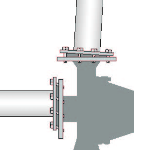
The tolerances around pipe misalignment vary according to the dictates of the standard or code being practiced, be it ASME, API, or any other. The gap in the offset at the weld joint is generally from 1/16 inch (1.6 mm) to 1/8 inch (3.2 mm) in most cases. Restrictive tolerances are usually encountered in highly pressurized systems or critical systems to keep proper alignment and minimize stress concentrations. Always refer to the applicable code or project specifications to verify the exact requirements.
Defining Hi-Lo Tolerance in Pipe Welding
These tolerances are regarded together because of how it’s regarded as single within the context of either internal or external facets. Hi and Lo in this case refers to a specular projection on a surface, and an outline around a half207, but the center does not meet. Hi-Lo in terms of pipe welding refers to the allowed offset range or the degree of misalignment between the two ends of a pipe at the joint at the weld. This degree of misalignment is used to determine the degree of weld strength that would be achieved and the flow rate at a certain pressure within the pipe, which qualifies it as a sound and enduring weld. Hi-Lo gauges or measuring instruments were explicitly designed for this task, thus measurement is made with the said tool. This accomplishment ensures that the imbalance in stresses is blocked, better flow is promoted, and that codes and welding standards are followed, such as ASME and API, or respective ones relating to the project at hand.
ASME Standards for Misalignment Tolerances
Within ASME Section IX and B31.3, ASME standards detail the acceptable limits for misalignment tolerances for welding work. The cited standards usually set the permissive limit on Hi-Lo (internal misalignment) to be within 1/16 inch (1.6 mm) to 1/8 inch (3.2 mm), based on the pipe diameter and wall thickness. With these misalignment tolerances, there is adequate strength on the welds, minimal likelihood of stress concentrators, and appropriate flow efficiency within a piping system. These limitations must be met for engineers to trust that their structures, systems, and machines will be safe. These parameters must be followed precisely by welders and inspectors if compliance with engineering specifications and system safety is to be achieved.
Calculating Tolerances for Different Pipe Wall Thicknesses
Determining tolerances for pipe wall thickness requires consideration of the criteria, including the minimum wall thickness, the tolerances of the manufacturing process, or the limit specified in ASME B31.3.
| Aspect | Details |
|---|---|
|
Min Thickness |
Based on pressure, material, and safety factors. |
|
Tolerance |
Typically -12.5% of nominal thickness. |
|
Standards |
ASME B31.3, ASTM guidelines. |
|
Corrosion |
Add allowance for expected corrosion. |
|
Verification |
Ensure actual thickness ≥ calculated minimum. |
How to Identify Misalignment in Weld Joints?
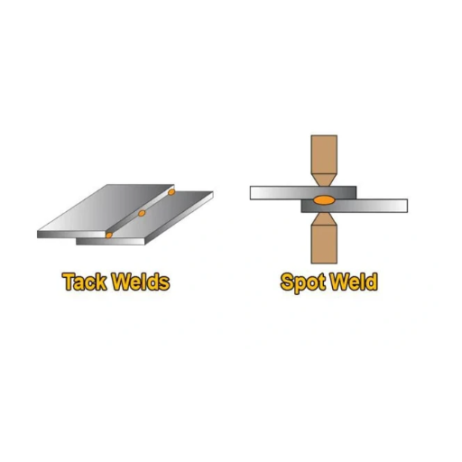
Weld joint misalignment can be checked by visually inspecting the constituent elements of the weld joint. Look for any apparent axial step between the edges of the pipes or other sub-parts being welded together. Apply a straightedge, level, or laser alignment device for an exact measurement. Gaps in the joint can signal misalignment, which no careful observer can ignore. Hence, detecting gaps is a definite molecular characteristic that the naked eye can observe. Consistent monitoring during the welding process and thorough pre-weld inspections greatly enhance the chances of achieving properly aligned welds while minimizing the risk of significant alignment-related problems.
Visual Inspection Techniques for Misaligned Welds
Even with the advanced technology available today, visual inspection combined with traditional means of critical alignment checking still serves its purpose in finding misalignment of welded joints. First, inspect the weld’s perimeter using a sufficient microscope illumination for visibility. Use lenses or electronic inspection tools to check for surface abnormalities, particularly within the boundaries of scratches, cracks, over-welding, or porosity. Critical evaluation of the contours of the weld and its constituents frequently presents alignment gaps in a cross-section. Modern systems, such as computer-aided scanning devices and augmented reality inspection programs powered by AI, enable faster and more accurate identification of details that inspectors would typically miss using traditional methods. Applying such advanced solutions together with established practices allows inspectors to detect worsened alignment issues and greatly enhance the overall quality of the welds.
Using Gauges to Measure Misalignment
Gauges serve as vital aids to check misalignment in welding with respect to industry standards to ensure accuracy. They help determine discrepancies in the welded joints to mark unconstructive flaws in the product, which will have dire effects on the structural integrity of the end product. Devices such as fillet weld gauges, gap gauges, and bridge cam gauges are used for specialized units of measurement.
These simple devices have different applications. For example, gap gauges determine the position of spaces within a joint to help with piece alignment before the welding begins. Bridge cam gauges stand out as multi-parameter evaluators as they can assess the angle of preparation, undercuts, laser fills, and gaps. Lastly, Fillet weld gauges are used to check the size and shape of the jug and lathe plate fillet welds to see if they match the set requirements.
Cited industry research states that misalignments within welded structures result in a loss of approximately 30% of the structure’s load-bearing capacity. With the aid of modern devices, inspectors can now achieve greater accuracy between 0.5 mm and 1mm, which is greatly improved relative to estimation accuracy without using tools. Moreover, speed and accuracy have drastically improved with modern innovations such as digital welding gauges with lasers. These digital devices often have data logging and data visualization capabilities in real time, which helps improve quality control checks and ensure compliance with standards such as ISO 5817 or AWS D1.1.
Precision would increase if welding operators adopted the use of gauges during the inspection phase and aligned their work with the set standard guidelines. At the same time, the risk of defects that could lead to expensive repairs or safety concerns would drastically reduce.
Reference Sources
-
Ship Hull Plating Weld Misalignment Effects When Subjected to Tension – Analyzes the consequences of weld discrepancies on the tensioned state of ship hulls.
-
Modeling of Welding-Induced Distortion Effects on Fatigue Behaviors of Lightweight Shipboard Structures – Looks into the affects of deformation misalignment processes on the fatigue life of light ship structures.
-
Experimental Study on the Effect of Misfit and Mismatch of Ship Plating Welds – Look into the mechanical impacts stemming from the mismatch and misalignment of welded ship plating joints.
- Top Welding Rotator Manufacturer And Supplier In China
Frequently Asked Questions (FAQs)
Q: What is hi-lo misalignment in pipe welding?
A: Hi-lo misalignment refers to the vertical displacement between two pipe ends at a joint, causing one pipe to be higher or lower. This misalignment can affect the overall integrity of the weld joint and lead to potential issues in the pipeline.
Q: How does hi-lo misalignment affect the weld quality?
A: Misalignment can lead to improper fusion and insufficient penetration of the weld metal. This can compromise a sound weld, which may increase the risk of defects and reduce the fatigue strength of welded joints.
Q: What are the common causes of deformation in pipe joints?
A: Common causes of deformation in pipe joints include thermal expansion during welding, improper pipe alignment, and external forces applied during installation. These factors can lead to angular distortion and other misalignments that affect the integrity of the weld.
Q: How can pipe beveling help reduce hi-lo misalignment?
A: Pipe beveling creates a sloped edge on the pipe ends, allowing for better fit-up during welding. This can help minimize the effects of pipe misalignment and ensure a more uniform weld bead and fusion, which enhances the quality of the joint.
Q: What role does post-weld heat treatment play in managing misalignment?
A: Post-weld heat treatment can relieve residual stress caused by the welding process, which may help mitigate the effects of distortion and misalignment. This treatment can also improve the joint’s fatigue performance and enhance its overall durability.
Q: What types of welds are most affected by hi-lo misalignment?
A: Butt joint welds are particularly susceptible to hi-lo misalignment, as any vertical displacement can significantly affect the penetration and fusion of the weld metal. Fillet weld joints can also be impacted, though to a lesser extent.
Q: How can proper pipe alignment be achieved before welding?
A: Proper pipe alignment can be achieved using alignment tools, clamps, and fixtures that hold the pipes in the correct position before welding. Ensuring accurate alignment is crucial to prevent hi-lo misalignment and ensure a successful weld.
Q: What is the significance of weld preparation in preventing misalignment?
A: Weld preparation, including proper cleaning and beveling, is essential to ensure that the surfaces to be welded are compatible and well-fitted. This minimizes the risk of misalignment and contributes to a more robust and sound weld.
Q: How can the fatigue strength of welded joints be affected by misalignment?
A: Misalignment can compromise the fatigue strength of welded joints, as it can introduce notch stresses and create weak points in the weld. This may lead to premature failure under cyclic loading conditions.
Q: What is the recommended approach to address existing hi-lo misalignment in a pipeline?
A: The recommended approach includes assessing the extent of the misalignment, correcting the alignment using appropriate tools or methods, and re-evaluating the weld quality. In some cases, re-welding or additional reinforcement may be necessary to ensure structural integrity.

![Robot Welding Parameters [Traceable Window]](https://zhouxianggroup.com/wp-content/uploads/2026/10/robot-welding-parameters-blog-featured.png)


