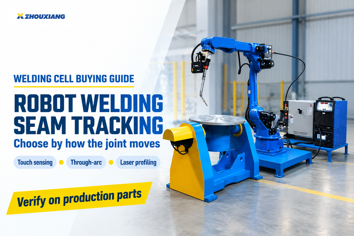
A bracket can sit off-center in a fixture and still yield a straight joint. A long seam can start in the correct place and move as the part heats up. Both can leave the torch off the joint, and each may require a different measurement. Robot welding seam tracking is the use of sensor feedback to adjust the torch path during welding.
Robot welding seam tracking uses sensor feedback to adjust the torch path during welding. Try touch sensing before welding for a repeatable part offset, or test through-arc tracking or live laser profiling during the weld when the signal reliably identifies the joint.
Quick Specs
- Before the arc
- Touch selected reference points or scan the seam to locate the joint.
- During the weld
- Use arc feedback or a laser vision sensor if the signal holds across the production path.
- Trial outputs
- Compare seam position, path correction, inspected welds and seconds per accepted part.
Key takeaways
- A robot can follow the joint and still give a weld that fails inspection.
- A displaced part may only need a short touch cycle. A seam that moves during welding requires a live observation.
- Compare installed options on the same parts, including an awkward clamp position and the last segment of the weld.
What Robot Welding Seam Tracking Measures
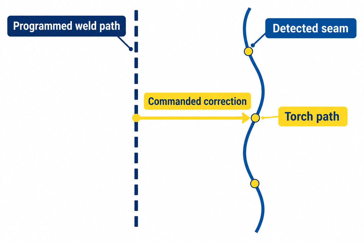
Seam tracking in robotic welding starts with two positions. The seam tracking system compares the programmed weld path with an estimate of where the joint is. Seam finding locates the part or joint before welding starts. Real-time tracking uses a signal that’s acquired during the run. An automated welding process can use both methods in sequence.
Ask the supplier to show which hardware handles detection and seam tracking, and when the robot starts making corrections. Yaskawa mentions using known points on a part to adjust the program before starting the weld in their seam finding and tracking guide.
How does a robot track a weld seam in real time?
The controller receives a signal related to the seam position and estimates where to move the torch. With through-arc tracking, the signal can be welding current. With laser profiling, it comes from the shape of a projected stripe in a camera image. The control system applies the correction to the robot path as the weld proceeds.
For a trial, put the programmed position, detected seam and commanded correction on the same timeline or position scale. Compare them to an independent reference wherever you can make the measurement. Those records let you determine whether a miss began with seam detection, the coordinate conversion or the movement itself. Calibration, teaching and positioning contributed to the difference between the reference and the measured paths in the experimental system studied by Mou and colleagues.
When Touch Sensing Is Enough
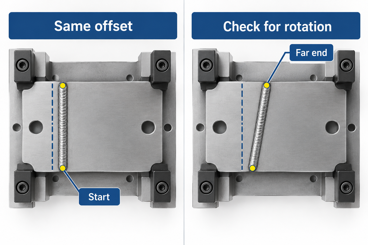
Touch sensing works for pre-weld seam finding when the joint moves with the part and the robot can reach known conductive surfaces. In a wire-touch cycle, the controller detects contact at chosen locations. A consistent shift at these locations supports correcting the programmed path for that part. Yaskawa’s wire-touch description
Consider a bracket that slides sideways against a worn locator. Check near the start and far end of the weld. If the same offset appears at both ends, then the bracket may have shifted. A different result at the far end calls for a check for tilt or local distortion. Measure at additional locations to distinguish the two before asking an integrator to shift the whole path.
ABICOR BINZEL estimated in 2020 that wire or nozzle touch sensing could add 6 to 10 seconds to a weld cycle on a 2D part. For short welds with multiple starts, include probing time in the weld-cycle assessment. Time the approach, retract and contact retries on the actual fixture. A clean test plate can mask a contact problem that appears on production surfaces. Tactile seam tracking systems that ride the joint during welding need to be assessed separately on access and contact. For this example, wire touch is considered a pre-weld measurement. If the shift is attributed to a worn locator, consider the result observed with a repaired fixture during the assessment.
When Through-Arc Tracking Fits the Weld
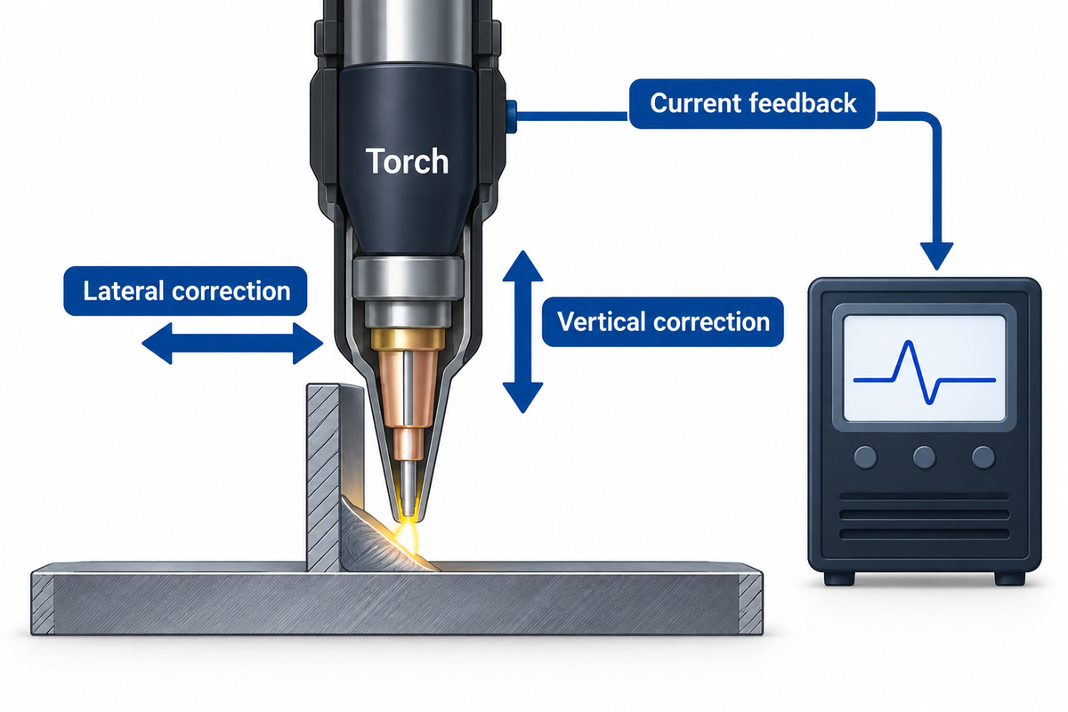
Through-arc tracking is an option if the arc welding signal changes in a repeatable way as the welding torch moves relative to the joint. FANUC describes its Through Arc Seam Tracking option as using current feedback to adjust the path laterally and vertically. FANUC says the tracking option is often used with touch sensing to locate the weld start. For additional information, see FANUC’s Through Arc Seam Tracking documentation.
Imagine a long fillet weld whose position changes as the assembly heats during robotic arc welding. A through-arc seam tracking trial should use the joint, source and approved job recipe the plant will run. If the proposed seam tracking technique requires a weave, ask the integrator to demonstrate that the weave fits the approved process. A run with a different recipe leaves the production signal untested.
Watch what happens when the torch reaches a tack or another interruption and the feedback becomes unreliable. Log whether the proposed option pauses, flags the part or follows a configured response. A case study published by the Association for Advancing Automation describes a KUKA cell at Trützschler that used touch sensing before welding and arc sensing during the run. It gives buyers an example of how those jobs can be split on one cell. The Association for Advancing Automation describes the Trützschler installation.
Check which specific welding processes the proposed arc sensing option supports.
When Laser Profiling Earns Its Place
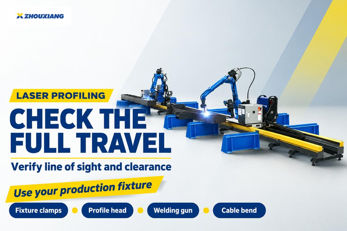
Laser seam tracking can trace seam geometry that a few touch points leave unresolved. In a profile head, a laser beam forms a line across the joint. A camera sees how the line changes, and image processing locates an edge or groove. In laser triangulation, the camera sees the line from a known angle.
DAIHEN describes a projected stripe and camera on its FD-QT system for the FD-series controller. DAIHEN lists 12 built-in joint geometries for that model. Compare those geometries with the joint shown on your drawing. DAIHEN robotic sensor documentation.
In automated laser welding, the beam that forms the laser weld has a different job from the projected line a profile sensor uses for welding guidance. Ask the supplier to identify both optical systems in the proposal if the cell uses them.
A stored pre-scan maps the joint before the arc starts. As the robot welds, an ahead-of-torch profiler samples the joint a short distance ahead, and the controller matches the profile to the path. Try moving the head through the full motion. A clamp can hide the laser line. Check clearance for the profile head even where the welding gun can already pass through. Ask your supplier to provide the combined dimensions of the sensor mount and welding head including the cable bend. Consult ABICOR BINZEL’s optical seam tracking guide.
A Sensors experiment reported mean feature-point deviations below 0.5 mm in each measured direction, X and Z, after precise positioning on the straight and curved grooves tested. How did the supplier measure tracking accuracy for your joint types? If its test reports only the detected weld position, ask for a second measurement at the torch. For a welding accuracy comparison, pair each detected position with a torch position measured on the same coordinate scale. An optics test should include cases that can lead to a lost profile. Another experiment recorded loss of detectable seam features when severe arc interference overexposed the image. The feature positioning paper gives results of both test grooves. The arc interference paper shows feature extraction failures.
Choose by How the Joint Moves
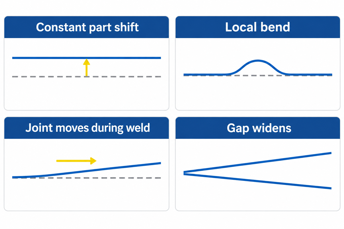
Measure the difference between the programmed and actual seam at the start, middle, and end of several parts. Then determine when that difference happens. Different tests are done based on whether the difference is steady, there’s a bend that exists already, or there’s a deviation that occurs during welding. Compare the candidate welding technology with the observed pattern.
If a bidder promises accurate seam tracking, supply it with those parts so it can demonstrate that accuracy. Use the table to transform the observed pattern into a trial brief.
| Variation type observed in the trial | Candidate to test | What to verify |
|---|---|---|
| Constant part shift | Check the fixture and try wire touch on known locations. | Measure the residual at the far end after applying the shift. |
| Part rotates in the fixture | Probe locations that reveal rotation. | Check whether the supported part correction leaves the seam within its tolerance at both ends. |
| Local bend present before welding | Try a laser pre-scan where the profile stays visible. | Compare the stored path with independently measured points around the bend. |
| Joint moves as the weld progresses | Compare through-arc and live laser tracking on the production recipe. | Compare the torch position at the planned speed and near the end of the weld. |
| Inconsistent arc signal | Test another supported sensing mode on the same joint. | Log where the signal becomes unreliable on the approved recipe. |
| Blocked optical view | Check another mount or another sensing method. | Recheck clearance and line of sight at clamps and corners. |
| Positioner brings the joint through an overlap | Try the proposed tracking mode with the positioner running. | Record when the correction begins and how it behaves through the overlap. |
| Gap widens beyond the approved range | Ask for the proposed stop, flag or approved adaptation. | Verify the logged condition and the disposition of the part. |
| No meaningful deviation | Keep the current setup as the comparison case. | Confirm output and inspection across the representative part mix. |
Detection of a gap adds a second decision. A weld tracking system may follow the center of a widening groove while the welding gap exceeds the range accepted for that job. An adaptive welding study used pre-weld gap measurements to calculate welding conditions during the weld. If a supplier proposes an adjustment to the welding parameters, ask which inputs it uses and compare that response with your approved limits, using the robot welding process window guide as a reference. Sharif et al., Quarterly Journal of the Japan Welding Society.
Test Tracking on Production Parts
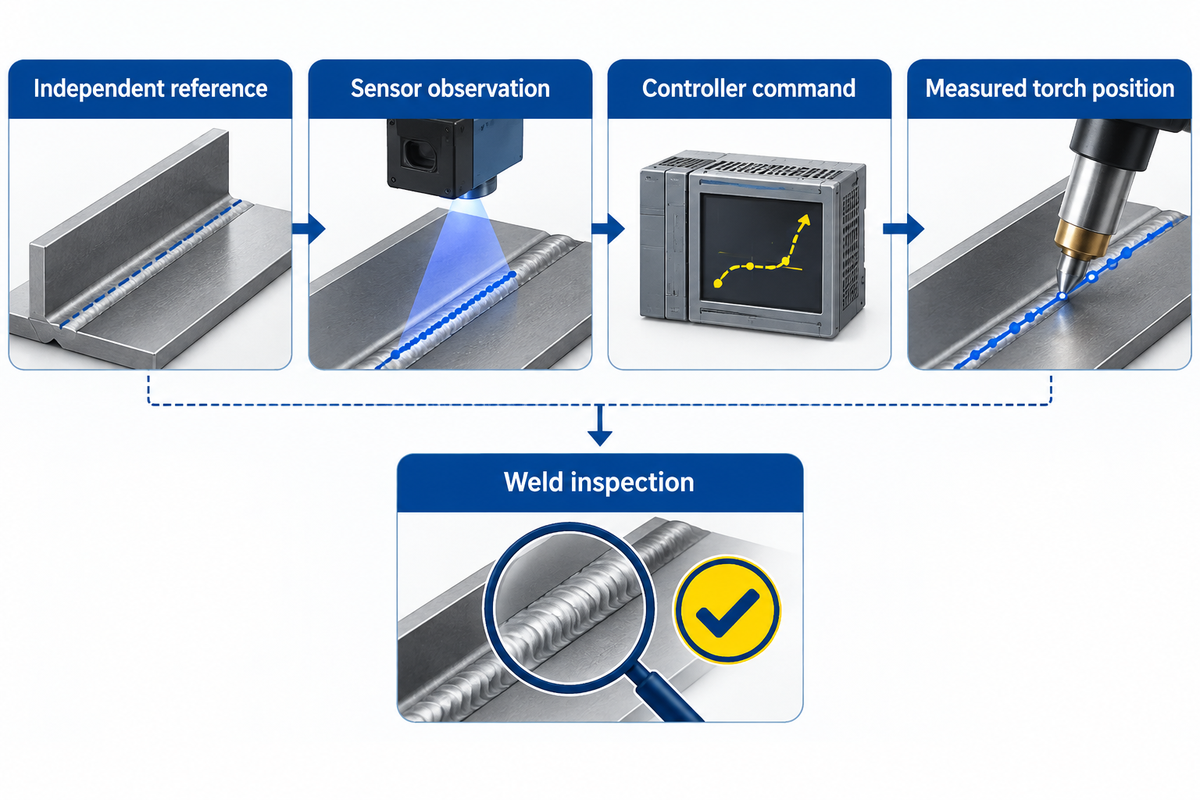
A useful acceptance trial allows us to trace each weld back to the part, fixture, job recipe and tracking data. Set tolerances with the quality team before the demonstration. Run the same mix of parts on both setups. Include the fixture position with the least clearance, the normal range of fit-up and any recurring condition that interrupts sensing.
| Record | What to capture | Decision it supports |
|---|---|---|
| Part and fixture | Part identifier, fixture identifier and run order. | Tie the controller log to the inspected part. |
| Joint condition | Seam type, fit-up and where access is limited. | Identify whether a miss is concentrated in particular parts. |
| Recipe and speed | Approved job recipe and planned travel speed. | Check that the two options ran the same job. |
| Independent seam reference | Measured reference at the start, middle and end. | Provide a basis for comparison with the sensor reading. |
| Sensor observation | Detected seam position and time or position along the run. | Find where the estimate first departs from the reference. |
| Controller command | Requested path correction at the same positions. | See when the controller began to apply the offset. |
| Measured torch position | Observed torch path in the shared reference frame. | Compare the actual residual with the agreed part limit. |
| Signal loss and disposition | Event location, recorded response and part disposition. | Check that a lost signal is visible in the trial record. |
| Cycle time and inspection | Elapsed time, accepted count, inspection findings and rework. | Compare seconds per accepted part alongside weld quality. |
A circumferential pipe trial captures the location where the positioner brings the seam back to the beginning. Timestamp the first valid correction and any missed profiles in the overlap. This helps determine when the position of the weld changed, prior to or after feedback was dropped.
Weld quality requires its own evidence. Tracking data shows where the system saw the joint and how it responded. The sensor might keep the torch centered over the weld pool while the finished weld still needs inspection. Use the agreed inspection method and check for incomplete weld penetration if required. ISO 17662:2025 addresses calibration, verification and validation of welding production equipment and leaves these requirements for finished product conformance inspections outside its scope.
Compare the Installed Cost of Tracking
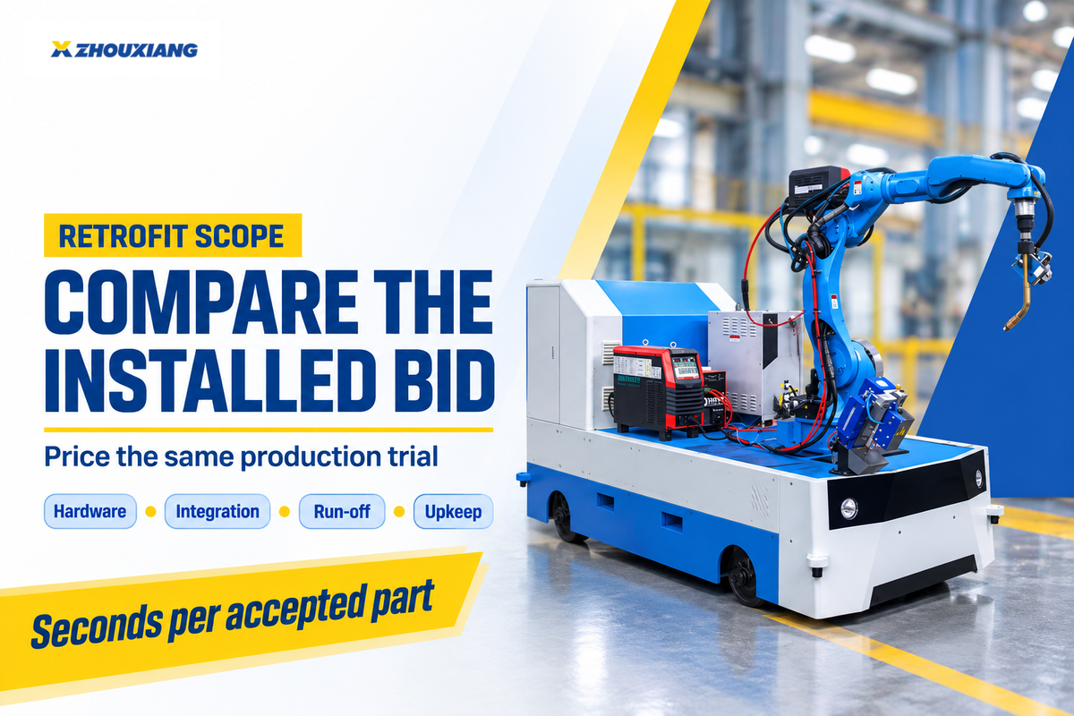
Two weld seam tracking systems can use similar hardware and still require different work to communicate with the robot and power source. The bid comparison needs both bidders to price the same production trial and use the same scope boundaries. NIST identifies device and sensor interfaces as a source of custom integration. (See NIST robotic systems integration program.)
What affects the price of a seam tracking retrofit?
The sensor, supported controller options, mechanical work and commissioning time affect the installed price for an industrial welding cell. Check whether quotes for the welding system cover mounting, cables, software and repeated trials. Ask for separate line items for planned downtime and maintenance so you can compare both offers.
| Quote line | Included scope to confirm |
|---|---|
| Hardware and options | Sensor system, bracket, cables and controller options by version. |
| Cell integration | Fixture or mounting changes, calibration, source interface and job programming. |
| Production acceptance | Run-off parts, inspection, operator handoff and any repeat run after correction. |
| Plant time and upkeep | Installation downtime, cleaning, spare parts and support after handoff. |
In this worked example, compare accepted output and elapsed welding time for two options that start with the same batch size and use the same inspection rule. Option A takes 72 minutes and produces 92 accepted parts, or 46.96 seconds per accepted part. Option B takes 78 minutes and produces 97 accepted parts, or 48.25 seconds per accepted part. A uses less time per accepted part. B supplies five more accepted parts from the same batch and takes six extra minutes. Use the metric that reflects the plant’s actual constraint.
Check Controller and Supplier Fit
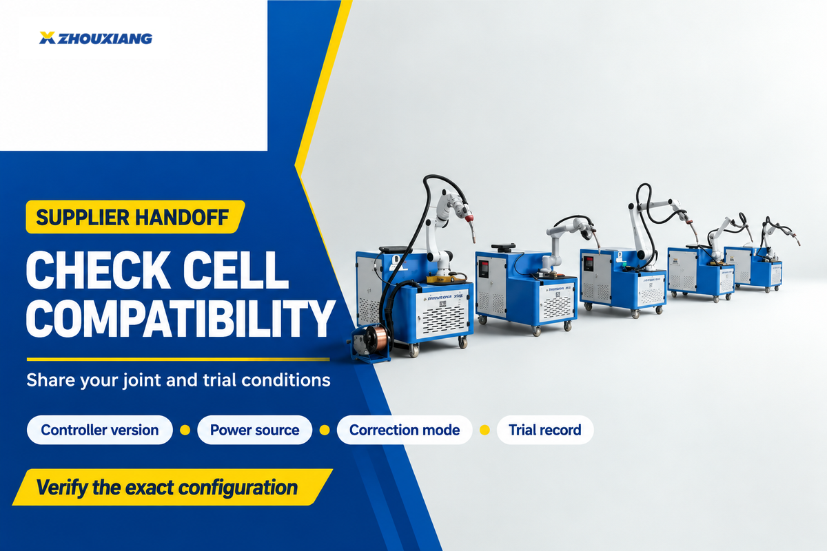
Evaluate compatibility for the exact robot, controller version, welding power source and correction mode supported. Traditional welding robots with older controllers: determine the option availability for the software release using the combination’s option code or interface document. For TIG welding, check if the option is specified for the process and power source. Put the acceptance test in the quote.
Assign responsibility for calibration, lost-signal behavior and support to the party that can verify the response and repeat the acceptance trial after a controller or power source change. Name the contact maintenance should use when a change to the welding machine affects sensor input. For a cell running several welding applications, identify which jobs need their own sensor setup or calibration.
Send a joint drawing, fixture photos, and the planned travel speed to the cell supplier. Indicate the least accessible area, and describe how production inspects the weld. The collaborative welding robot family of Zhouxiang lists laser vision tracking. Bring the trial record when you ask about a Zhouxiang welding robot configuration so the proposal identifies the specific controller, sensor and joint conditions it covers.
Frequently Asked Questions
When is seam tracking necessary in an automated welding cell?
Live tracking becomes useful when the joint moves away from the programmed path during the run and the proposed feedback can detect the change. Check fixtures and production part seams first. If the entire joint shifts together before the arc starts, a part-location correction may solve the problem with a shorter sensing cycle.
Can seam tracking work on a robotic pipe weld?
Yes, as long as the sensor can see the joint around the pipe and the robot and positioner are coordinated. A pipe operator from the ABB Robotics Community reported that the arc began at the right position. The torch then briefly moved away from the seam. The tracking feedback corrected the path. If the proposed system uses a similar handoff, ask for a run on your fixture. Document both sides of the transition and any overlap. ABB Robotics Community discussion.
Can an existing welding robot be retrofitted with seam tracking?
A retrofit may be possible if the controller supports the proposed input and can apply the needed path correction. There must also be enough space to mount the hardware and route its cables throughout the full range of motion. Ask for the controller version, power source and option details, then test the combination on your part at the planned speed.
Can a laser seam tracker verify penetration?
No. The laser seam tracker reports joint geometry or position. Verify weld penetration with the method specified for the part.
Does seam tracking fix a joint gap that grows along the weld?
No. Tracking can keep the torch centered as the opening grows. Compare the measured gap with the job’s accepted range before choosing a stop, flag or approved adjustment.
References & Sources
- Mou et al. on reference and measured paths in robotic weld tracking.
- Association for Advancing Automation case study on touch and arc sensors
- Sensors study on precise positioning of features in straight and curved grooves
- Sensors experiment on detection under arc interference
- Quarterly Journal of the Japan Welding Society study on gap-based welding conditions
- ISO 17662:2025 scope for production welding equipment
- NIST research on robotic systems interoperability and integration