Updated October 2026
Weld preheat is heating the base metal around a joint prior to welding. Select the preheat requirements through the applicable welding procedure, then measure the specified locations before starting and between passes. Keep the minimum temperature, any maximum interpass limit and the measurement instructions together: a heater setting alone cannot tell you whether the joint is ready.
- Temperature basis: the applicable welding procedure specification, or WPS.
- Selection inputs: material, joint thickness, hydrogen control, restraint and heat input.
- Measurement: specified location, timing, instrument and required thermal condition.
- Restart: re-establish the required conditions after interruptions.
Welding preheat slows cooling around a weld joint and can reduce hydrogen-induced cracking in susceptible steels. Use the applicable WPS to select limits, then measure the workpiece at the required locations and times.
Welding preheat: what it does and when it is required
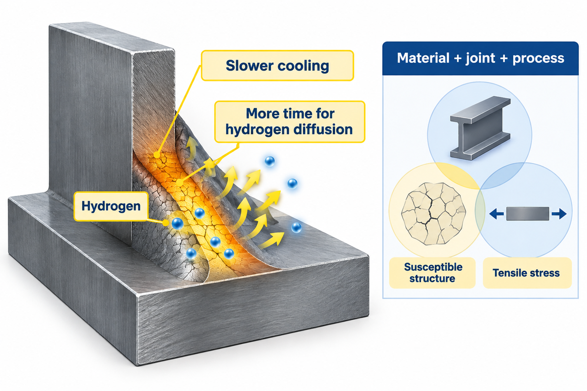
Preheat slows the cooling rate of the weld and adjacent Heat Affected Zone (HAZ). In susceptible steels, controlling the cooling rate can limit the formation of martensite, a hard and potentially brittle microstructure. Slower cooling also gives more time at elevated temperature, allowing hydrogen to diffuse away. The need to preheat depends primarily on the material, joint and welding process, rather than the appearance of a cold plate.
TWI’s explanation of hydrogen cracking identifies hydrogen, a susceptible structure and tensile stress as interacting factors. Carbon and alloy content affect hardenability, or how readily a steel can harden. Material thickness and joint geometry affect heat flow. These metallurgical and thermal factors affect susceptibility to cracking. Weld metal can also be susceptible to cracking; therefore, controlling base metal alone doesn’t resolve all cracking mechanisms.
A dry looking weld area may still need preheat. Surface dryness says little about how quickly the weldment will cool or how much hydrogen a poorly handled consumable may introduce. Clean the joint using the preparation method specified. Don’t use a torch to burn away grease or paint to clean the joint.
There are differences in the timing and purposes of preheat and post-heat processes. Post heat intended to promote hydrogen diffusion is different from a specified post-weld heat treatment. The operations require their own procedure instructions. Preheat is done before welding. Multipass welding may require a minimum interpass temperature and/or continuous preheat maintenance. Postheating to control hydrogen and any specified PWHT are governed by their own procedure instructions. Neither replaces suitable joint preparation or control of weld penetration and fusion.
Select preheat temperature from the governing procedure
Begin with a WPS that covers the actual material, joint and welding process. Welding codes define permitted procedure routes; the job specification defines which code requirements apply. When no suitable procedure is available, the welding coordinator must establish the permitted code route before production begins. A published preheat chart may assist only within stated limits of material groups, thickness definitions, and process conditions.
What is the preheat temperature in welding?
The base-metal temperature before welding, the preheat temperature, is defined in the WPS for the job in question. Values range widely; TWI notes that preheat may be as high as 200°C, for example, when welding thick-section steels with a high carbon equivalent (IIW CE) value. The appropriate preheat temperature varies with composition, thickness, hydrogen level, restraint and heat input. A borrowed value from another joint may satisfy some of the above, but not all.
In his AWS discussion of preheat and interpass selection, Robert E. Shaw, Jr. distinguishes prequalified minimums from alternate calculation and qualification routes. For the route below the listed prequalified temperatures, he states:
“Qualification testing is still required using preheat and interpass temperatures lower than those listed in Table 5.8.”
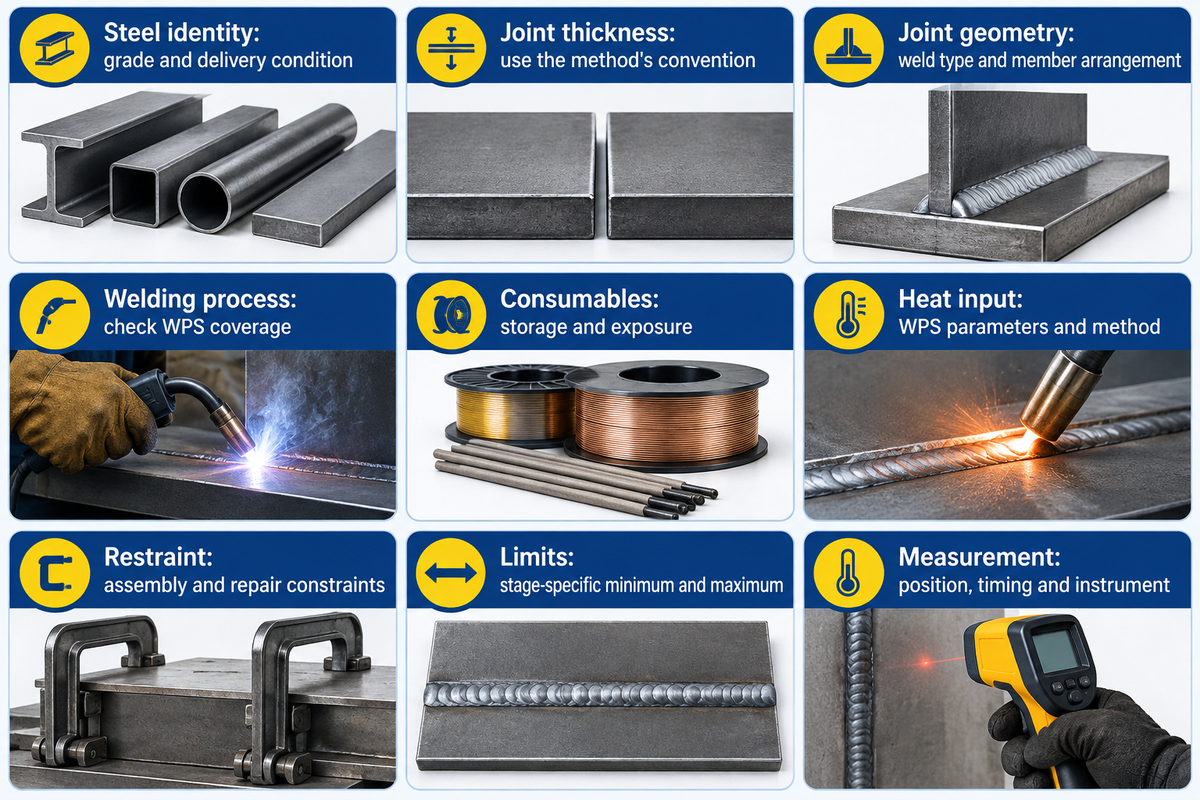
| Input | Required information | Decision it supports |
|---|---|---|
| Steel identity | Grade and delivery condition | Select the applicable material group and thermal limits |
| Joint thickness | Thickness convention required by the chosen method | Avoid substituting one plate thickness for combined thickness |
| Joint geometry | Weld type and member arrangement | Account for heat flow and access to the required checking point |
| Welding process | Process and WPS coverage | Use the correct prequalification or qualification route |
| Consumable control | Classification, storage and exposure condition | Support the hydrogen-control input used in selection |
| Heat input | WPS parameters and applicable calculation method | Keep the thermal cycle within the procedure basis |
| Restraint | Assembly and repair constraints | Include the joint conditions affecting cracking risk |
| Temperature limits | Stage-specific minimum and any applicable maximum | Separate initial preheat from interpass requirements |
| Measurement instruction | Position, timing and instrument requirements | Make the temperature check reproducible |
Carbon equivalent calculations are method-specific. CE, CET, CEN and Pcm have different application ranges; their outputs aren’t interchangeable. Establishing a preheat temperature also requires the thickness definition used by that method, which may differ from the thickness of one plate.
Check material, thickness and hydrogen inputs
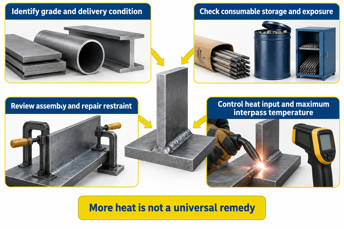
Before applying preheat, determine the steel grade and delivery condition. Carbon and alloy steels vary in their response to the same thermal cycle. A low carbon steel description is too general to determine the procedure to be selected. Low-alloy steels and quenched-and-tempered grades may require more strict control of the heat input and maximum interpass temperature in order to retain the desired mechanical properties.
Hydrogen control involves consumable storage and exposure. A nominal low-hydrogen classification doesn’t describe what happened to the electrode coating or flux on the shop floor. MDOT’s field-welding guidance deals with the storage of electrodes separately from preheat, because moisture pickup can introduce hydrogen. Use the handling requirements of the consumable of interest; bridge-electrode oven settings don’t automatically apply to submerged-arc flux.
For a restrained repair, identify the original steel grade, existing weld and restraint, all of which belong in the procedure review. Reusing an arc welding setting, for example, because the replacement plate has the same thickness misses those differences. Residual stress and a susceptible microstructure can combine with hydrogen, even when the visible bead looks sound.
A high heat input isn’t a universal remedy for a risk of cracking. TWI describes cases where increased preheat or heat input does not reduce hydrogen-cracking risk. Transformation behavior and the distance hydrogen needs to diffuse can alter the outcome. Excessive heat can also reduce toughness or soften some heat treated steels, as discussed by Meyer and Koltz in The Welder.
Compare induction, resistance and flame preheating
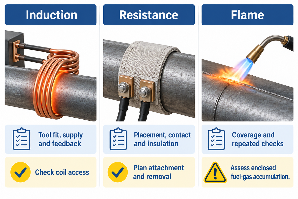
Choose a heating method capable of reaching and maintaining the required condition over the joint geometry. Induction heating requires an appropriate coil or heating-tool arrangement. Resistance heating requires heater contact and an insulation material appropriate to the work. Ceramic pads transfer heat to the steel by conductive and radiant heat transfer. Electrical strip heaters are other heating arrangements for structural work. Flame preheating requires the controlled application of a torch and the use of appropriate precautions during fabrication.
| Method | Planning priority | Job constraint to resolve |
|---|---|---|
| Induction | Tool fit, electrical supply and temperature feedback | Coil access around flanges, fixtures and moving parts |
| Resistance | Heater placement, contact, insulation and control zones | Attachment and removal during handling or repositioning |
| Flame | Torch coverage, fuel equipment and repeated temperature checks | Local hot spots; unburned fuel-gas accumulation where the weld preparation opens into an enclosed fabrication |
At Lambeau Field, Miron Construction used induction equipment during steel-column reinforcement work. Miller’s project account reports a target of 150°F, approximately 66°C, and a coil arrangement built around the columns. The practical lesson is the installation: the heating tool had to suit the member and remain useful through the welding sequence. A beam-line buyer faces the same type of access question around fixtures and flange joints. The case temperature belongs to that reinforcement procedure; it isn’t a starting setting for an unidentified production weld.
HSE’s oxy-propane guidance identifies a particular hazard when a weld preparation opens into an enclosed steel fabrication: unburned fuel can collect behind the joint. This case geometry must be analyzed as part of the heating method assessment. Electrical heating still requires special equipment and precautions against hot surfaces and electrical hazards.
Verify preheat temperature at the specified location
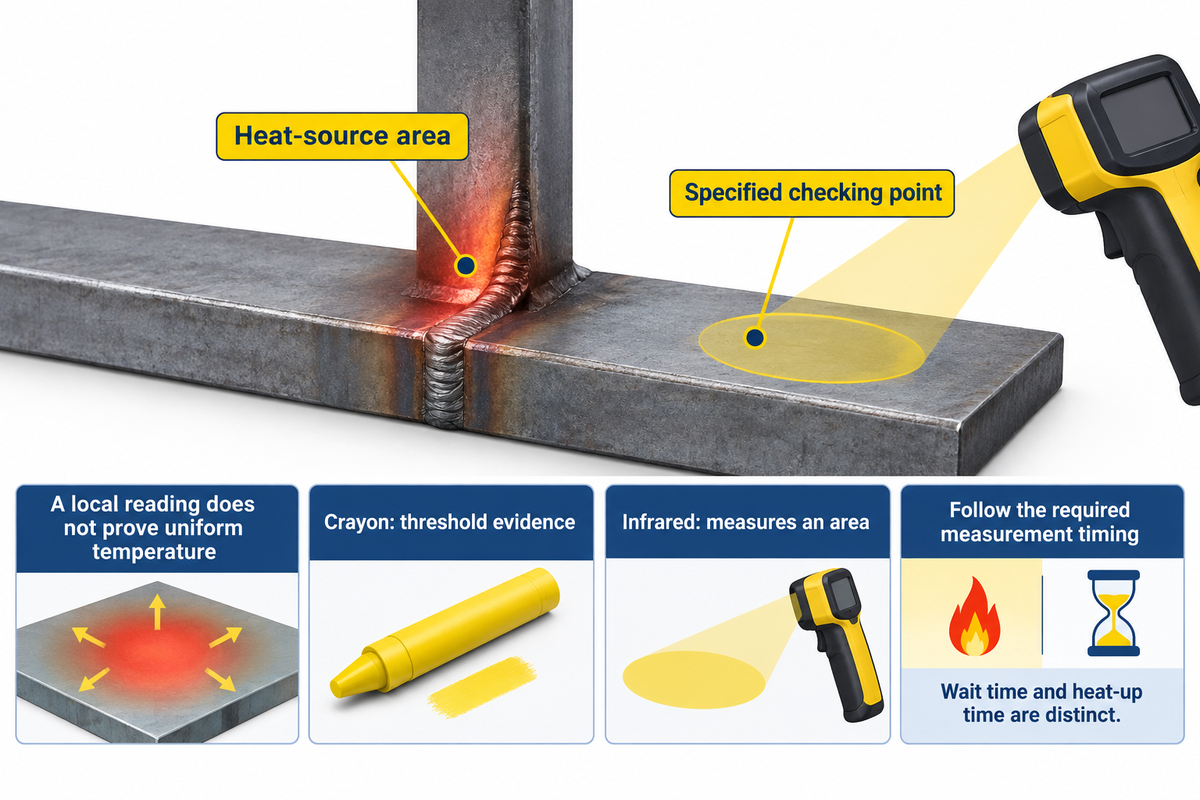
At the specified time, measure the workpiece at the specified location(s) for the joint, including the required check prior to welding. A temperature difference can exist between the heat-source area and the required checking point. Don’t assume a uniform temperature throughout the section from one local reading. Select an instrument appropriate for the surface and the temperature range, and follow the requirements for instrument verification or calibration.
A temperature-indicating crayon provides threshold evidence. Once its mark has melted, that mark can’t indicate whether the joint subsequently cooled or became even hotter. TWI’s Tempil-stick guidance makes a distinction between this and continuing temperature measurement. A contact instrument or thermocouple arrangement may be appropriate when the procedure requires repeated readings or continuous control.
Infrared instruments need care on shiny metal. Fluke explains the effects of emissivity and measurement spot size. The laser indicates where the instrument is aimed, while the instrument measures temperature over an area. Use the surface and distance instructions. An unexplained low reading isn’t an indication for more heating.
How long should preheating be done?
Heat until the required region reaches the specified temperature, then follow any required equalization or holding time. Heat-up time varies with the section, heater and conditions. For their original products, SSAB quotes a minimum wait time before measurement of two minutes per 25 mm of thickness. This time is distinct from the time needed to heat the steel.
- Identify the checking point. Use the joint’s measurement instruction, including side and distance.
- Apply heat and allow the required wait. Follow the specified heating region and timing.
- Read and record. Compare the measured value with the limits for that welding stage.
Control interpass temperature and restart after a break
Maintain the minimum interpass temperature and stay within any applicable maximum between passes. The minimum preheat before starting and the interpass minimum must each be taken from the WPS. The lower limit helps control cracking risk; the upper limit can protect the thermal conditions needed for mechanical properties. TWI’s interpass guidance also distinguishes continuous temperature maintenance from a check immediately before the next pass.
Two-Limit Preheat Check
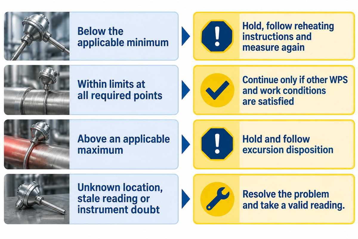
The Two-Limit Preheat Check is an editorial checklist for this guide and not a test defined by code. It compares the current reading to the applicable lower and upper limits before the next welding step.
This comparison is made after WPS, consumables and working conditions have been checked. Ambient temperature restrictions and conditions of work surfaces are separate requirements. Apply each limit only where the procedure specifies it. If a required limit or measurement instruction is missing, the welding coordinator resolves it before work continues.
| Observed condition | Action |
|---|---|
| Below the applicable minimum | Hold the welding operation, follow the procedure’s reheating instructions and measure again |
| Within the applicable limits at all required points | Continue only when the other WPS and work conditions are satisfied |
| Above an applicable maximum | Hold welding and follow the specified excursion disposition |
| Unknown location, stale reading or instrument doubt | Resolve the measurement problem and take a valid reading |
Example: A fabricator has paused a multipass flange weld while a handling issue is cleared. In the meantime, the earlier crayon mark is still there when the operator returns. This mark isn’t a new interpass reading. The operator checks the locations specified in the WPS and finds one that’s below the minimum. Welding is paused while the approved restart sequence is carried out for the joint. If continuous temperature maintenance was required and was lost, simply reheating is not automatically sufficient; the responsible welding specialist handles that departure. The record identifies the joint and the interruption, because a later in-range interpass reading does not by itself show that the whole interruption was acceptable.
Record preheat checks before welding continues
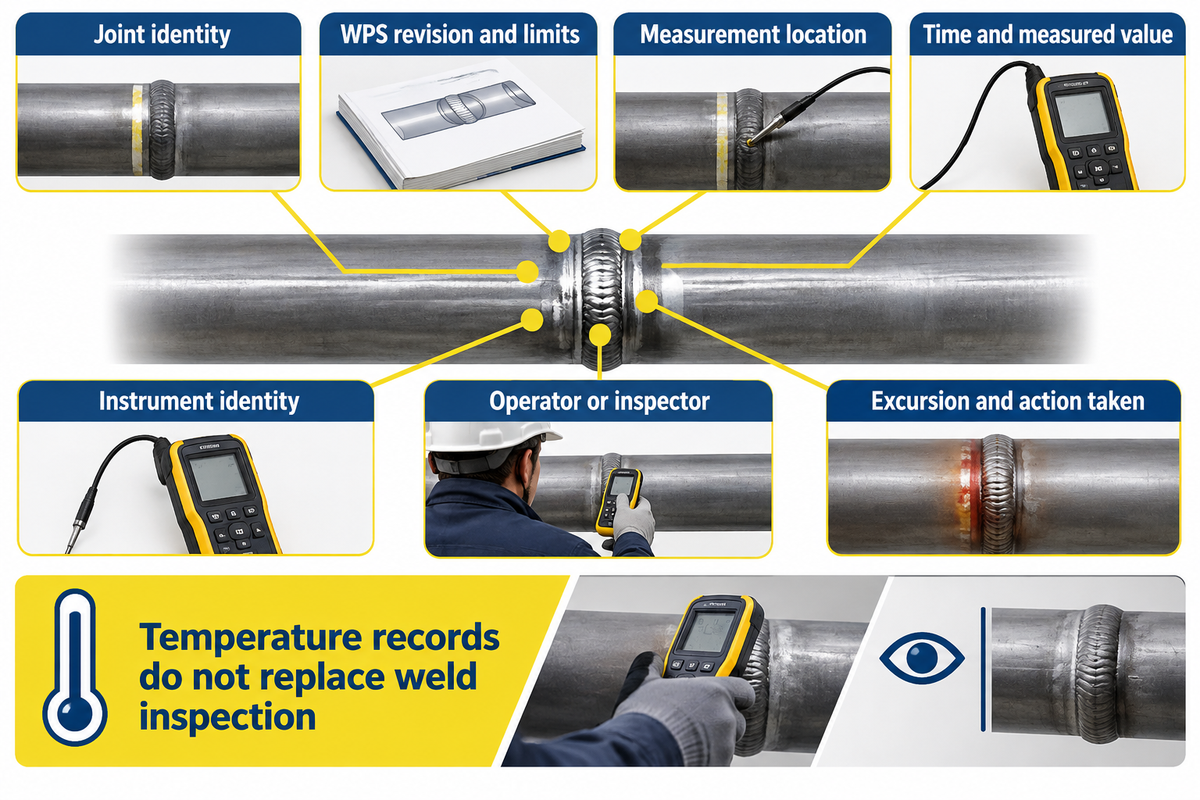
Record enough information to connect each reading to a joint, a procedure and a welding stage. At minimum, a useful shop record identifies the joint, WPS revision, applicable limits, measurement location, time, instrument and measured value. Include the operator or inspector identity and the action taken when a reading falls outside the permitted condition.
Temperature gradients matter: readings from different points should remain identifiable rather than being averaged into a reassuring single number. A trace labeled only “temperature” doesn’t differentiate weld area from a remote location of the member.
- Identify the joint and current WPS revision.
- Keep location, time and instrument with each reading.
- Record interruptions and the required follow-up.
- Substitute the heater setpoint for a workpiece reading.
- Reuse a melted mark as evidence of current temperature.
- Erase an excursion because the joint later cooled.
Temperature records support process control and weld quality. They don’t replace inspection for weld defects. Assessment of weld integrity still follows the mandatory method of inspection and timing; hydrogen cracking can develop after welding. MDOT’s separate weld-inspection requirements illustrate this distinction between making the weld and accepting it.
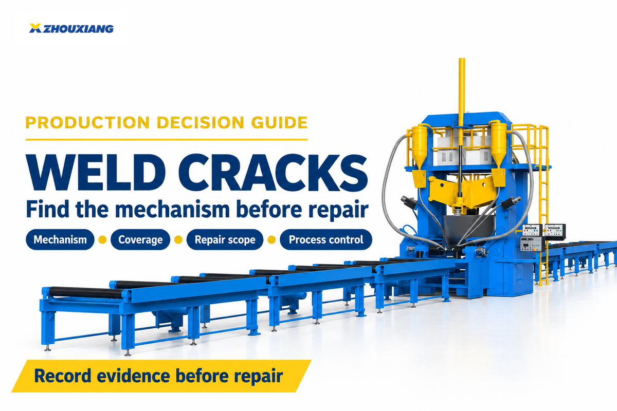
Plan preheat around an H-beam welding line
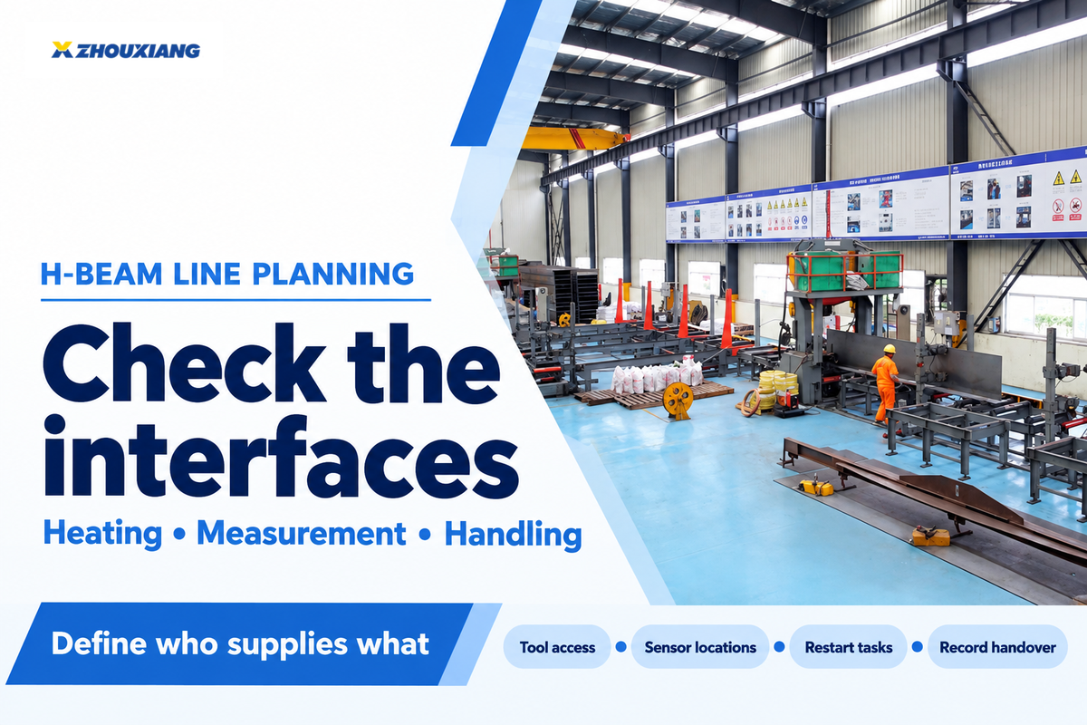
Integrate heating and measurement into the sequence of assembly, tack welding, final welding and handling tasks. On an H-beam welding line, the useful question is whether the required joint temperature can be established and checked without fixtures, flange geometry or movement blocking access. Tack welds need their own applicable procedure conditions.
The following scope must be considered in a quotation request. The line supplier and heating equipment supplier must identify who provides what and who demonstrates the complete assembly.
| Equipment scope category | Required quotation detail | Trial observation |
|---|---|---|
| Heat the joint | Heating tools, power or fuel connection, control and any cooling requirements | Required points reach the job’s temperature conditions |
| Position the tooling | Access around minimum and maximum planned beam sections | Attachment and removal fit the production sequence |
| Measure and retain readings | Sensors, instruments, channel identification and record export | Each reading remains connected to its joint and location |
| Move and restart | Cable routing, fixture clearance and restart responsibilities | Handling and interruptions preserve or restore the required conditions |
| Temperature sensors | Number, type, attachment and replacement supply | Sensors reach the specified positions with fixtures in place |
| Instrument checks | Required verification or calibration arrangements | Instrument identity matches the shop record |
| Record handover | File format, joint identifiers and retrieval access | A saved trial reading can be retrieved for its joint |
| Operator training | Tool setup, measurement and interruption handling | The assigned operator performs the agreed sequence |
| Compare installed cost | Installation, training, consumables, spares and monitoring included or excluded | Both bids cover the same demonstrated job scope |
Example: purchasing receives a lower priced heater quote without sensors while a second bid includes measurement channels and fitted tooling. Finance can’t compare the bids as equivalent packages. The production manager must have the attachment, heating, and restart tasks timed on the intended joint. Quality needs the correct measurement locations and a retrievable record. Purchasing can then add the missing items to the first bid and compare installed scope. A shorter heating period helps the line only when tooling, handling and measurement fit the same sequence. Put those tasks into the trial acceptance plan before selecting the package.
For a Zhouxiang line discussion, send the planned beam sections, steel grades, welding process, joint drawings and WPS thermal requirements through the project enquiry page. Include the required production sequence and who will supply the heating and temperature-monitoring equipment.
ISO 13916:2025: check the adopted measurement edition
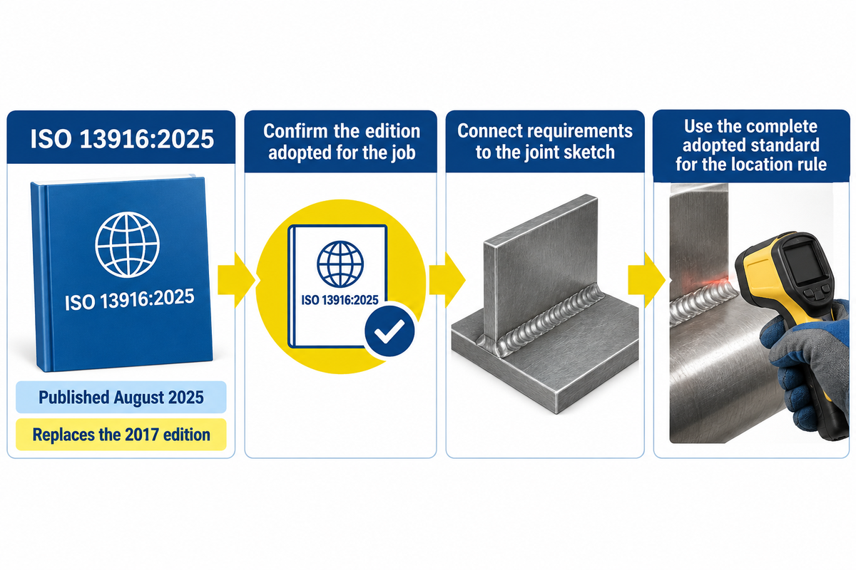
Measurement instructions need the edition adopted for the job, including its conditions for locating the temperature check. ISO 13916:2025, published in August 2025, addresses measurement of preheating, interpass and preheat-maintenance temperatures. It replaces the 2017 edition; a contract referring to an older edition still needs an agreed treatment of that reference.
The official national-standards preview identifies a change to the measurement position requirements in subclause 4.1. The case in point relates to joint thicknesses up to and including 50 mm where the heat source is outside the weld groove. This provides a reason to evaluate an existing temperature check instruction, particularly if it’s a copy from an older chart.
During a procedure update, the welding coordinator should connect the adopted measurement requirements to the shop instruction’s joint sketch and checking points. Instrument placement, heating-tool access and operator instructions must describe the same arrangement. Use the complete adopted standard for the actual location rule; the revision summary identifies which arrangement needs attention.
Welding preheat FAQ
Can you weld without preheat?
View answer
Can you weld with wet rods in welding?
View answer
Does paint have to be removed before welding?
View answer
Does every weld require post-weld heat treatment?
View answer
What are the risks of overheating a weld?
View answer
Can induction heating be used for welding preheating?
View answer
What happens if preheating is skipped when it is required?
View answer
Put the heating task into your beam-line plan
Bring the joint drawings and procedure requirements to the equipment discussion. Zhouxiang can discuss the line layout and the interfaces that need to accommodate heating, measurement and handling.
This guide addresses procedure selection and shop-floor verification for fabrication planning. Production welding uses the applicable WPS and project requirements. Company information: about Zhouxiang.
References & Sources
- AWS: preheat and interpass procedure selection
- TWI: hydrogen cracks in steels; temperature-indicating crayons; preheat and interpass control; limitations of increasing preheat and heat input
- HSE: oxy-propane preheating of enclosed fabrications
- MDOT: structural steel field-welding guidance
- The Welder: preheat and interpass temperature, Part II
- ISO 13916:2025 catalogue and official national-standards preview