Among welding defects, cracks demand attention because they can grow under stress and weaken a joint. Finding the cause comes before choosing a repair. Separate what the indication looks like, when it appeared, and which mechanism could explain it. Those observations guide inspection and the next production decision.
Record the material, joint, crack position and inspection time. Establish the required disposition and repair procedure before removing the evidence. A smooth repair surface is only part of the acceptance decision.
Weld cracks: causes and their place among weld defects
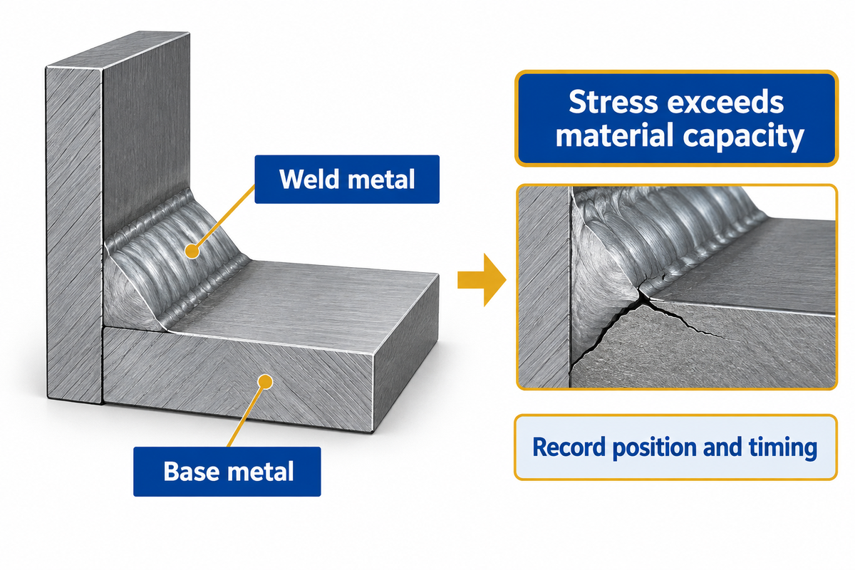
Weld cracking occurs when local stresses are greater than what a material can withstand. The vulnerable region may lie within the weld or in the surrounding base metal. Among the other possibilities, thermal contraction and/or restriction, susceptible microstructures and/or hydrogen can also contribute to the failure mechanism; identifying a crack therefore requires more than naming its visible position.
The American Welding Society’s explanation of weld cracks distinguishes a fracture-type discontinuity from other weld defects. Porosity is a cavity, and an edge groove can be undercut. The presence of either, or both, cannot always explain a fracture.
Suppose a beam is about to leave an assembly station at the end of a shift. A quality manager gets a call from an operator who sees a line beside a run of fillet welds and wants to grind it before his next shift. The quality manager should take the opposite action. He should photograph the indication and mark its position with respect to the joint and retain the process and material records. Grinding the indication would erase useful information. The production manager should isolate the affected work and plan access while the responsible technical personnel establish the basis for the necessary examination. This isolates useful preparation from an unapproved repair. The decision is about the particular joint and its service, rather than whether the same machine made acceptable beams yesterday.
- Describe location and direction separately.
- Record whether the indication appeared during fabrication, after cooling or in service.
- Compare actual conditions with the applicable welding procedure and inspection plan.
Hot cracking versus hydrogen cracking
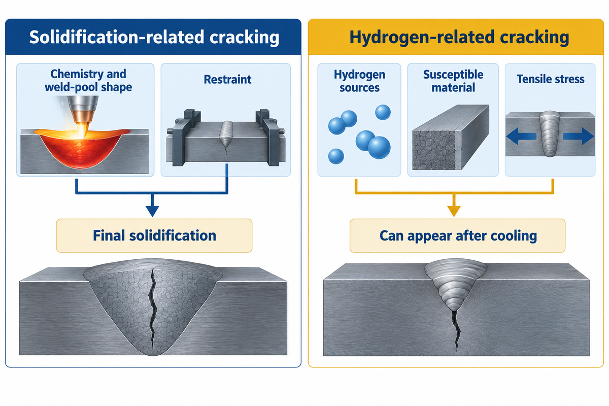
Hot cracking develops at elevated temperature and may occur as weld metal solidifies; the process of hydrogen cracking in susceptible steels is caused by hydrogen, a crack-sensitive structure and tensile stress. Mechanisms differ and a solution that resolves one may not resolve the other. Therefore, a generic suggestion to heat or slow down the process is inadequate.
- Forms during the vulnerable final stage of solidification.
- Investigate chemistry, dilution, weld-pool shape and restraint.
- Check joint preparation and the actual welding technique.
- Can emerge after the weld has cooled.
- Investigate hydrogen sources and susceptible material conditions.
- Check thermal controls, consumable handling and tensile restraint.
TWI’s solidification-cracking guidance explains how the last material to solidify may lack the strength to resist contraction and may result in some form of cracking. Variations in the composition of the plate and filler, impurities such as sulfur, and weld geometry affect susceptibility. Liquation describes a different hot cracking mechanism in which some material locally melts. Not all centerline cracks are caused by this mechanism.
According to TWI’s hydrogen-crack identification guide, for ferritic steels, the mechanism involves hydrogen, a hard brittle microstructure, and tensile stress. For carbon and low alloy steels, their actual grade, thickness and thermal cycle need to be assessed. Cold cracking is a general time description, and not an indication that hydrogen played a role in all cold fractures.
More heat is not a general remedy. Increasing the heat input can slow the cooling rate; however, a larger bead provides hydrogen a longer path to escape. TWI considers this trade-off in their hydrogen guidance. Set preheat and interpass temperatures through the correct procedure; changing them individually can resolve one metallurgical problem while introducing a different one.
Crater crack in welding: location, direction and mechanism
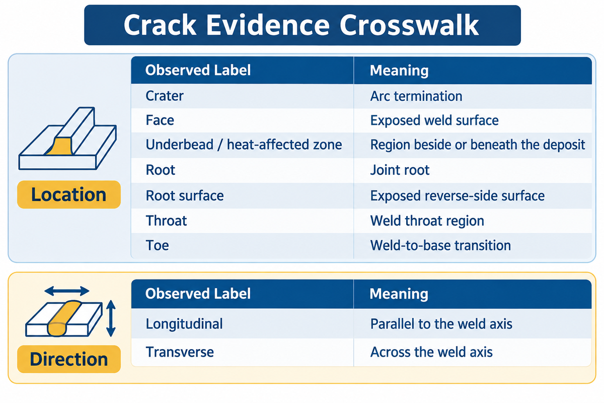
A crater crack in welding forms at an arc termination, and roots, toes, and faces label other positions. Longitudinal and transverse describe directions relative to the weld axis. A root crack may also be longitudinal; its formation time and the material in context help distinguish its mechanism of formation.
What are the different types of cracks that can form in welding?
A suspected crack should be classified by mechanism, location and direction rather than lumping the three together. Hot and hydrogen-related cracking describe the mechanisms and formation conditions. Crater, root, toe and heat-affected zone define where an indication lies. Longitudinal indicates parallel to the weld axis; transverse means across it.
The Crack Evidence Crosswalk (below) is a recording aid based on the AWS crack terminology. Use the observation column to provide a clear description, and then collect the information necessary to define and explain the mechanism. This is a description framework, not an acceptance classification.
Crack Evidence Crosswalk
| Observed label | What it records | Useful next evidence |
|---|---|---|
| Crater | Arc termination | Stop sequence and crater-fill record |
| Face | Exposed weld surface | Bead profile and procedure record |
| Underbead / heat-affected zone | Region beside or beneath the deposit | Material, thermal and hydrogen history |
| Root | Joint root | Fit-up, penetration and root examination |
| Root surface | Exposed reverse-side surface | Reverse-side access and preparation |
| Throat | Weld throat region | Section geometry and examination coverage |
| Toe | Weld-to-base transition | Local profile, loading and restraint |
| Longitudinal | Parallel to the weld axis | Position, extent and formation time |
| Transverse | Across the weld axis | Orientation relative to the inspection field |
When dealing with a toe indication, first compare it to undercut and weld-toe geometry, and then investigate the mechanism. When dealing with a component that is already in service, include a loading history. A fatigue-related crack is a different concern from a discontinuity that was first identified during fabrication.
NDE for weld crack detection: surface and ultrasonic testing
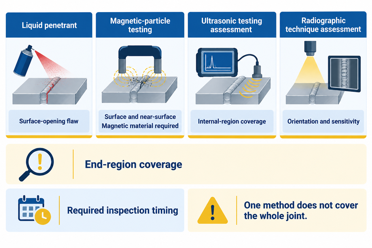
Non-destructive testing is material dependent, and takes into account access, location, and flaw orientation. Consider the required coverage and timing. A method capable of finding one class of indication does not cover every part of a joint. An acceptable observation now cannot describe a crack that develops afterward.
TWI’s penetrant and magnetic-particle guidance makes two useful distinctions. First, penetrant requires a surface opening, while magnetic-particle testing can reveal surface and near-surface flaws. Second, magnetic-particle testing requires a magnetic material. Surface preparation is important because contaminants and roughness can confuse or obliterate indications.
| Inspection question | Candidate approach | Planning check |
|---|---|---|
| Is the surface accessible? | Visual examination | Lighting, cleanliness and viewing access |
| Does the flaw open to the surface? | Liquid penetrant | Clean opening and suitable surface condition |
| Is the material ferromagnetic? | Magnetic particle | Material suitability before method selection |
| Could direction hide an indication? | Multiple magnetization directions | Field orientation relative to the flaw |
| Is an internal region the target? | Ultrasonic testing assessment | Geometry, access and qualified coverage |
| Is radiographic testing proposed? | Radiographic technique assessment | Orientation and sensitivity to the target flaw |
| Is the indication near a weld end? | Specific end-region coverage review | Plate edge, tabs and accessible scanning surfaces |
| Could delayed cracking occur? | Specified inspection timing | Procedure, material and governing requirements |
| Has repair changed the joint? | Repair examination plan | Excavation confirmation and final acceptance |
Imagine a shop finds a linear indication near the end of a joint that it has recently welded. The quality manager wants to figure out when the indication originated, what surfaces were analyzed, and if the end region was covered with the technique that was used. The record could show a number of situations including an access gap, an unsuitable orientation, or a later-developing indication. Each one points to a different corrective action. The production scheduler needs that differentiation before promising a restart. A second photo of a clear surface would not be very helpful if the unresolved concern is regarding an internal region or a required later evaluation.
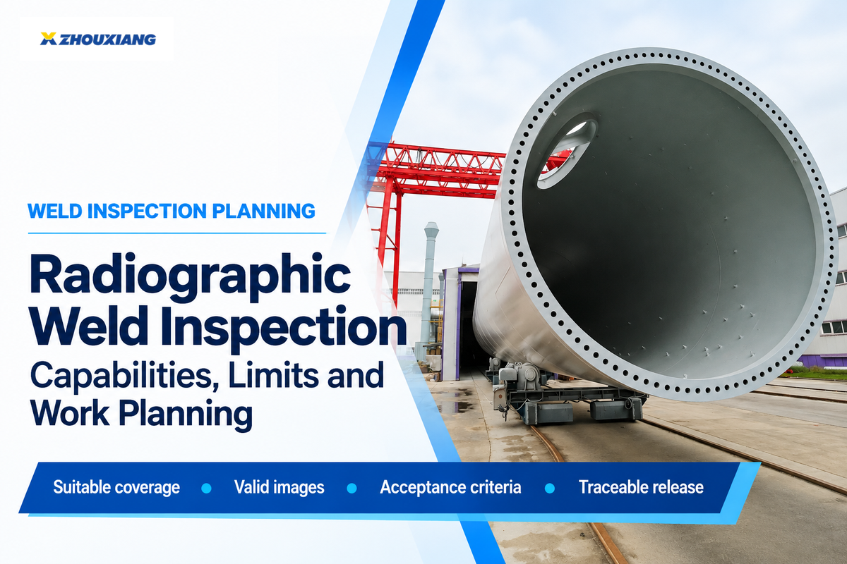
A 1979 Federal Highway Administration advisory records both instances of “delayed findings” and weld-end coverage problems in the fabrication of bridges. It provides historical examples that support asking those questions rather than applying the old waiting periods to newer projects. A more detailed description of radiographic weld inspection is given in the existing guide.
Weld crack repair: remove the cause before rewelding
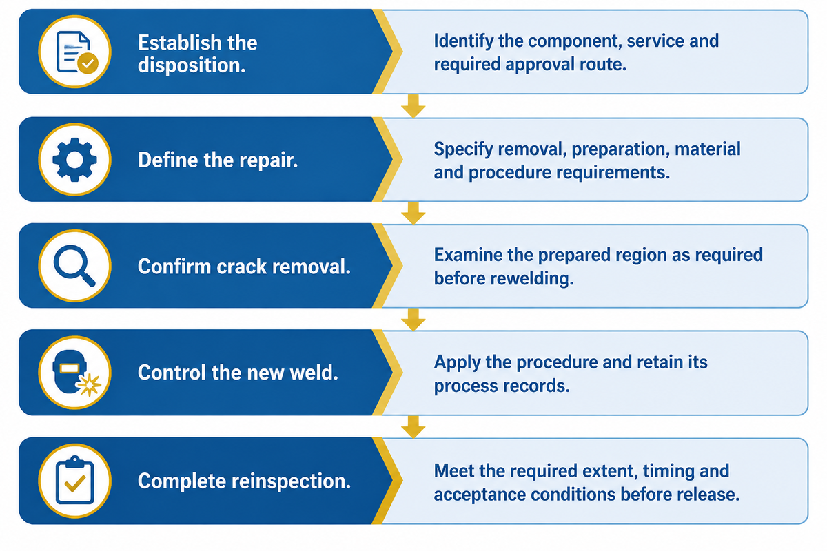
A weld crack repair consists of determining a disposition and an appropriate repair procedure, as well as the complete removal of the crack, confirmation of the excavation, controlled rewelding and the required reinspection. Addressing the cause of the defect is part of crack repair; if this is not done, replacing the visible indication would be of no use.
Can you weld over a crack in steel?
No. The crack has to be completely removed before rewelding under an approved qualified repair procedure. The AWS repair guidance states the entire crack has to be removed, cleaned and rewelded under an approved qualified repair procedure. The permitted repair and examination to confirm the repair remain dependent on the actual component and its applicable requirements.
A cover pass can conceal an indication while leaving a stress concentrator beneath it. Establish the extent of the crack and the means of its removal before sealing with new metal. The responsible technical person must determine, based on service conditions, the remaining section and access, whether the conditions allow a repair. Covering or locally grinding an indication of unknown origin to remove it is not a root cause investigation.
- Establish the disposition. Identify the component, service and required approval route.
- Define the repair. Specify removal, preparation, material and procedure requirements.
- Confirm crack removal. Examine the prepared region as required before rewelding.
- Control the new weld. Apply the procedure and retain its process records.
- Complete reinspection. Meet the required extent, timing and acceptance conditions before release.
Stress field changes are impacted by repair geometry. Song and Dong’s 2017 study abstract noted differences in residual stresses before and after repair. Its design guidance is directional rather than a size: a weld repair should be designed as long as possible, as narrow as possible and as shallow as possible.
Weld crack repair cost factors: repair versus replacement
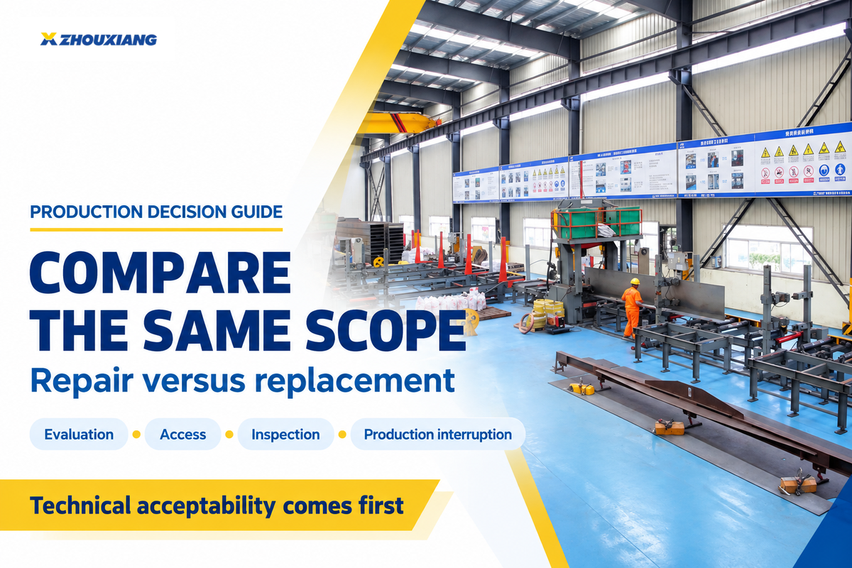
Consider replacement and repair only after alternatives have been examined and found acceptable. Consider the bounds of work and cost in both repair and replacement.
“The cost is not only in dollars to retrofit/repair but also in time and inconvenience to the traveling public.”
For a fabrication shop, comparable issues are expenses and disruptions. The AWS D1.7/D1.7M:2024 repair guide includes weldability, evaluation, testing and sampling alongside damage repair. List those items as separate lines when comparing repair quotations.
Repair Interruption Cost Model
| Cost or decision item | Repair quotation | Replacement quotation |
|---|---|---|
| Technical evaluation | Cause, extent and repair feasibility | Replacement design and interfaces |
| Material identification | Existing material and consumables | Replacement specification and traceability |
| Access and handling | Expose the affected joint | Remove and install the member |
| Preparation | Excavation and removal confirmation | New joint and connection preparation |
| Welding work | Procedure and local rewelding scope | Fabrication and installation scope |
| Examination | Required repair checks and timing | Required new-work checks and timing |
| Restoration | Coating and local access restoration | Connections, coating and alignment |
| Interruption | Time until the repaired item can return | Lead time and installation stoppage |
| Release responsibility | Who signs the repair acceptance | Who signs the replacement acceptance |
Considering expensive repairs, imagine receiving an offer for repair which covers excavation and rewelding. The offer for replacement would cover delivery and installation and inspection. The totals immediately favor the incomplete scope. Finance returns the table to both bidders so that each reflects the same bounds. Production identifies the activities which prevent the facility from being available, such as restoration of access and the required examination schedule. Quality confirms that both alternatives are technically acceptable. If replacement can be fabricated while the existing line is blocked for some other reason, its interruption may differ from its delivery lead time. If repair requires hard-to-access welding, the welding hours may be a small part of the job. The comparison uses the complete scopes rather than an assumed universal savings percentage.
Prevent common welding cracks through process control
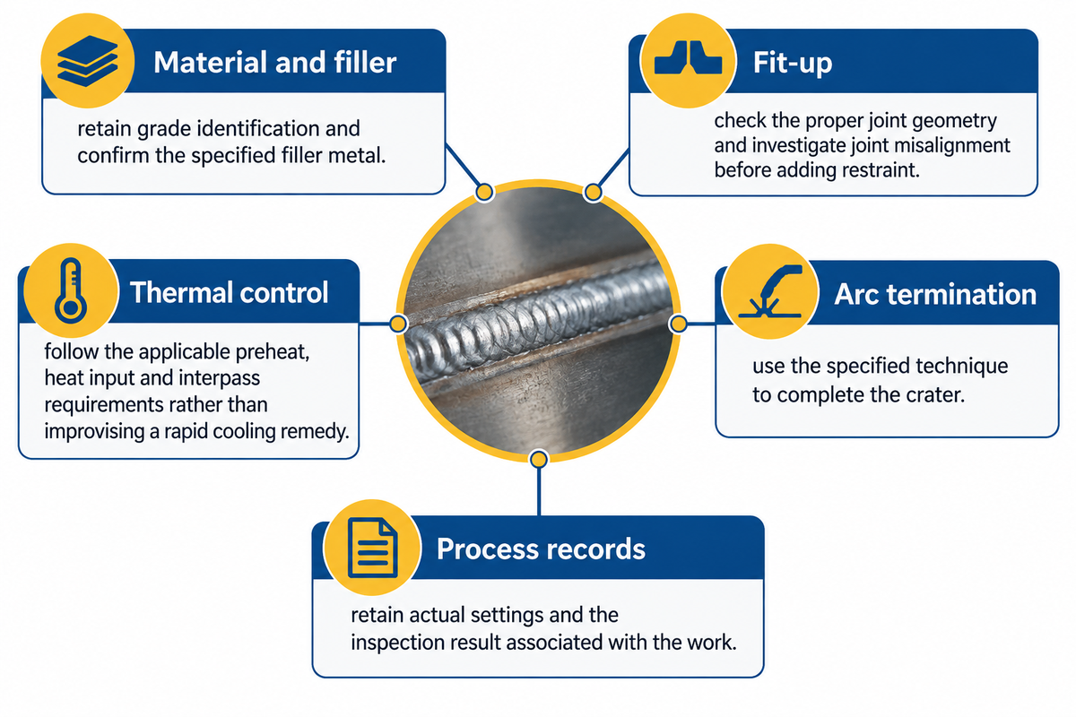
Prevent common welding cracks by linking corrective actions to the suspected mechanism and testing the actual process against its procedure. Review material identity, consumable condition, fit-up, restraint and thermal history. Change a documented cause deliberately; changing several settings together makes recurrence difficult to analyze.
For hydrogen-induced cracking, TWI identifies hydrogen sources and susceptible steel conditions. Check welding rod or wire handling and storage requirements. An electrode chosen for strength alone may be incompatible with the joint’s other requirements; the guide to electrode selection provides the wider context of selection.
- Material and filler: retain grade identification and confirm the specified filler metal.
- Fit-up: check the proper joint geometry and investigate joint misalignment before adding restraint.
- Thermal control: follow the applicable preheat, heat input and interpass requirements rather than improvising a rapid cooling remedy.
- Arc termination: use the specified technique to complete the crater.
- Process records: retain actual settings and the inspection result associated with the work.
A gas-shielded welding process requires specific checks. For MIG welding or TIG welding, compare shielding gas identity, supply, and specified flow rates with the procedure. Check a contaminant source or contaminated shielding gas, instead of treating every surface imperfection as the same failure. Torch angle and welding speed also warrant process-related reviews. A MIG welder setting can’t be copied to submerged arc equipment.
TWI’s hot-cracking guidance integrates plate and filler chemistry with weld-pool behavior. Different types of welding have different dilution and bead-shape conditions. High residual stress, joint design and internal stresses are included in the investigation, but not a rationale for recommending one adjustment across all welding projects.
Industry Outlook: H-beam line control and inspection requirements

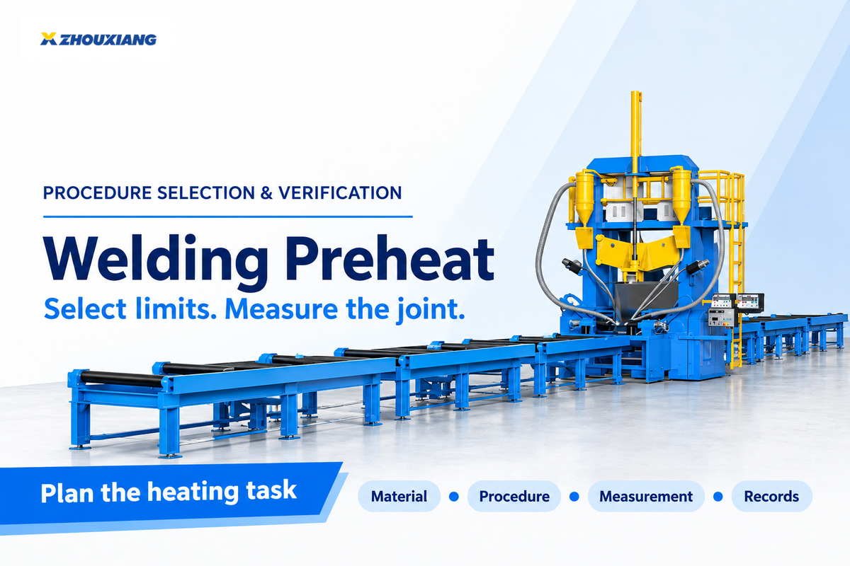
H-beam welding equipment purchasing should bring machine control and the adopted welding requirements and inspection access in the same specification. Published by AWS, D1.1/D1.1M:2025-AMD1 includes revisions for structural steel. For a new project, identify which edition is required and the pathway to acceptance, and only then specify automation features or guarantee a production rate.
The AWS official D1.1 page describes procedure qualification, fabrication, inspection and acceptance within its scope. Publication of a newer edition does not itself revise an existing contract. Put the adopted requirements into the equipment enquiry so that fixtures, handling and examination access can be evaluated together.
The table below reproduces the model ranges from Zhouxiang’s product page. It describes equipment selection dimensions and assembly/welding travel, rather than a count of accepted beams per shift.
| Published parameter | PHJ0815 | PHJ0820 |
|---|---|---|
| Web height | 160–1500 mm | 200–2000 mm |
| Web thickness | 6–16 mm | 6–30 mm |
| Flange width | 150–800 mm | 200–800 mm |
| Flange thickness | 6–25 mm | 8–40 mm |
Zhouxiang’s published table indicates a workpiece length of 6000 – 15000 mm and an assembly/welding speed of 0.35 – 3 m/min for both PHJ models.
Check the largest and smallest beams, the specified joints and the handling sequence against the appropriate model. A part inside the dimensional envelope still needs suitable fit-up, a welding procedure and examination access. The H-beam assembly and welding line query must include the above in addition to the accepted outputs.
Inspection records are beginning to be included in automation. In an August 2026 Inspection Trends Article, Servo-Robot President Jeff Noruk describes linking visual measurements and process data. The critical question for a buyer is: which inspection records, if any, does the proposed configuration produce, and how do they meet the required inspection? Measuring surface geometry and examining internal cracks answer different inspection questions.
Specify the beam drawing, material grade, joint details, required dimensional tolerances, procedure reference and inspection access in the trial plan. Agree how accepted output will be measured before using travel speed in a capacity comparison.
Frequently asked questions
Are welds always as strong as the welded materials?
A weld is not automatically as strong as the materials it joins.
Joint performance depends on the material combination, joint design, welding procedure, workmanship and the structure’s requirements. Surface appearance and joint strength answer different inspection questions. Where strength or fatigue performance matters, follow the applicable design and qualification requirements. A smooth weld bead alone provides no measurement of the strength of the completed connection.
Does medium carbon steel crack during welding?
Medium carbon steel can be susceptible, but cracking is not inevitable.
Composition and cooling conditions can produce a hard, crack-sensitive region near the weld. Hydrogen and tensile stress can add to that susceptibility; TWI notes that steels with a carbon equivalent (CE) below 0.4 are generally not susceptible to HAZ hydrogen cracking, as long as low hydrogen welding consumables or processes are used. Material identification and an appropriate welding procedure matter more than a generic temperature recommendation. Select the consumable, thermal controls and inspection requirements for the actual grade, thickness and service, then compare the production record with that procedure.
What causes porosity in welding?
Porosity forms when gas becomes trapped as weld metal solidifies.
Surface contamination, moisture, inadequate shielding or unsuitable process conditions can contribute, depending on the process. Porosity is a cavity-type imperfection; a crack is a fracture-like discontinuity. They may share some process problems, but a nearby crack can still have a different cause. Investigate the indications separately and apply the inspection and acceptance requirements for the work.
What is slag inclusion in welding and what are its causes?
Slag inclusion is nonmetallic material trapped in a weld.
In slag-forming processes, inadequate cleaning, poor access or unsuitable bead placement can contribute. It differs from a crack, although either indication may require evaluation.
How can we reduce welding defects during welding operations?
Begin with the defect mechanism and a documented comparison with the procedure.
Confirm the material and joint condition before changing settings. For suspected hydrogen cracking, review consumable handling, contamination, thermal controls and the factors that make the joint susceptible. For solidification cracks, investigate chemistry, dilution, bead shape and restraint. Record each change so its effect can be distinguished from normal variation. Examination should follow the method, extent and timing required for the work, with material and access limitations understood. On an automated line, include fit-up, travel control, handling and inspection access in the review. Faster travel alone is not a measure of acceptable joints. Recurring crack formation calls for cause investigation and an appropriate disposition before another repair cycle. Quality and production should agree the release evidence before the station is scheduled to restart.
Plan the beam line around the joint
Send your beam drawings, material range, welding requirements and inspection constraints to discuss a beam-line configuration. Define the trial and accepted-output target alongside the equipment specification.
References & Sources
- What Is Weld Cracking — American Welding Society, Inspection Trends, May 2024.
- Defects: Solidification Cracking — TWI, Job Knowledge 44.
- Defects: Hydrogen Cracks in Steels — Identification — TWI, Job Knowledge 45.
- Non-Destructive Examination, Part 1: Liquid Penetrant and Magnetic Particle Inspection — TWI.
- Quality Control and Quality Assurance Inspections on Welded-Steel Fracture-Critical Members — Federal Highway Administration, Technical Advisory 5140.11, November 27, 1979.
- Residual Stresses at Weld Repairs and Effects of Repair Geometry — S. Song and P. Dong, Science and Technology of Welding and Joining, 2017; public abstract.
- D1.7/D1.7M:2024 — Guide for Strengthening and Repairing Existing Structures — American Welding Society; public publication description.
- AWS D1.1/D1.1M:2025-AMD1 — Structural Welding Code–Steel — American Welding Society.
- The Next Evolution of Welding Automation and Inspection — Jeff Noruk, Inspection Trends, August 2026.