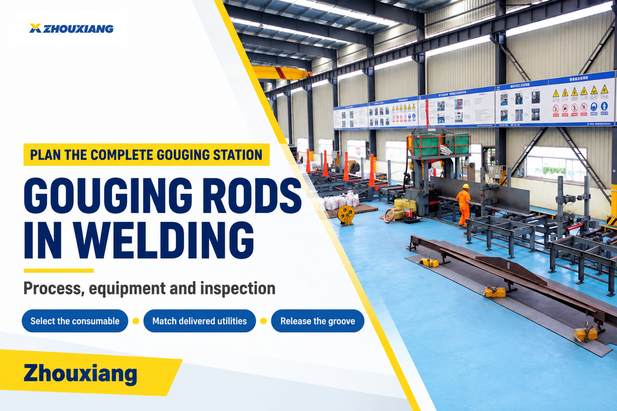
Purpose: remove metal for preparation or repair.
Consumables: carbon electrodes with compressed air, or purpose-designed flux-coated gouging electrodes.
Equipment decision: match the electrode, power source, torch and delivered air supply.
Quality hold: release the prepared groove before second-side welding when the project requires it.
Gouging rod welding removes metal from a weld (or work piece) in order to prepare a joint, excavate a defect or open a root for welding from the other side. Deciding which rod to use starts with the process family. A copper-coated carbon rod and a flux-coated metal gouging rod remove molten metal in two different ways.
The equipment gap can be larger than the consumable price suggests. Arcair’s K4000 comparison chart lists 25 cfm at 80 psi alongside a maximum torch rating of 1000 A . The torch’s electrical rating, the compressor’s delivered flow and the welder’s sustained output are separate checks.
Gouging rod welding is metal removal, rather than filler deposition. Air carbon-arc gouging uses a carbon electrode and a separate air jet; special MMA gouging rods generate an ejecting gas stream from their coating. Identify the family before choosing settings or equipment.
- A beam fillet weld doesn’t automatically call for back-gouging.
- Use the current and polarity instructions for the selected electrode family.
- Compare compressor flow at operating pressure, alongside the power-source manual.
- Surface preparation and examination must work together: grinding can affect what penetrant testing reveals.
What Gouging Rods Do
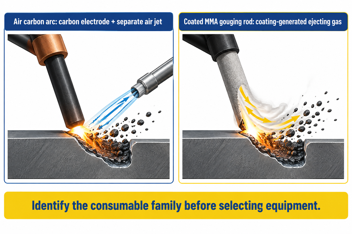
A gouging electrode supplies an arc that melts the material to be removed. Something must then clear that liquid metal from the groove. In air carbon arc gouging, the separate compressed-air stream is used to blow the molten metal from the groove. TWI identifies this air jet as the process’s distinguishing feature in its air carbon-arc description.
Purpose-designed manual metal arc, or MMA, gouging electrodes take another route. Their flux coating is thick enough to generate the gas stream and arc pressure used to push metal out of the way. A typical stick welding electrode is designed to lay down filler; don’t think that it can stand in for a cutting or gouging piece just because it fits into the holder.
For cutting rods, record the designated removal process rather than choosing by appearance alone. The product instructions indicate the necessary machinery. For a localized repair, the ability to simply change out consumables may be a production factor; for long-term excavation, the clearing capacity and surface are more important.
Back-Gouging a Weld Root
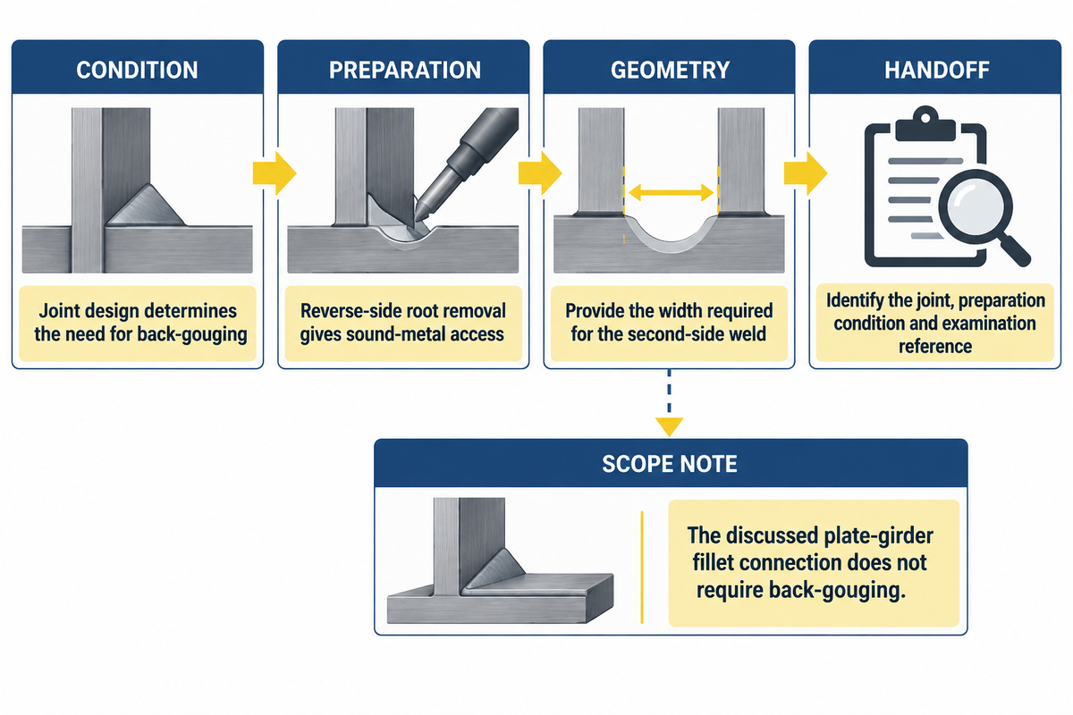
The specified weld joint determines whether reverse-side root removal belongs in the production sequence. Set that requirement before ordering the gouging station.
What is a back gouge in welding?
A back gouge is the removal of material on the reverse side of a welded joint, which reveals the root region to prepare for welding. Its purpose is to give the second-side weld access to the required sound metal and joint geometry. Whether that preparation is needed comes from the specified joint design and welding procedure.
Joint design comes before a gouging purchase. In an AWS discussion of plate-girder web-to-flange connections, Ronnie Medlock explains that fillet-weld preparation doesn’t require back-gouging. That observation addresses the connection being discussed; it isn’t a reason to change a drawing that specifies a groove weld.
For the production supervisor, the appropriate handoff is a clearly identified excavation and examination stage. The operator needs the joint identification and required access profile. The examiner needs the preparation condition, exam method where specified, and acceptance reference.
Hypertherm’s back-gouging explanation also emphasizes sound-metal access and sufficient groove width for the second-side weld. Removing a narrow slot without the access required by the welding procedure can leave a preparation problem for the next operation.
Rod Diameter and Current Belong to One Process
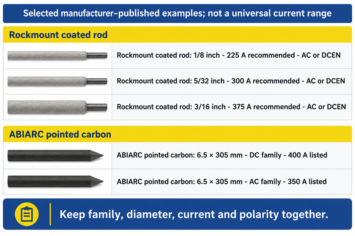
Rockmount lists 225 A for its 1/8-inch Electra AAA electrode , with AC or DCEN in the product’s recommended settings. That is an example of why a diameter alone is insufficient: the product family and electrical instructions must travel with the number.
| Type / product family | Size | Published current | Electrical designation |
|---|---|---|---|
| Rockmount Electra AAA, coated gouging rod | 1/8 inch | 225 A recommended | AC or DCEN |
| Rockmount Electra AAA, coated gouging rod | 5/32 inch | 300 A recommended | AC or DCEN |
| Rockmount Electra AAA, coated gouging rod | 3/16 inch | 375 A recommended | AC or DCEN |
| ABIARC pointed carbon, DC | 4 × 305 mm | 250 A listed | DC product family |
| ABIARC pointed carbon, DC | 5 × 305 mm | 300 A listed | DC product family |
| ABIARC pointed carbon, DC | 6.5 × 305 mm | 400 A listed | DC product family |
| ABIARC pointed carbon, DC | 8 × 305 mm | 500 A listed | DC product family |
| ABIARC pointed carbon, AC | 6.5 × 305 mm | 350 A listed | AC product family |
| ABIARC pointed carbon, AC | 9.5 × 305 mm | 450 A listed | AC product family |
Sources: Rockmount Electra AAA recommended settings and ABICOR BINZEL ABIARC technical tables. These rows are product examples, not the endpoints of a general amperage range.
The gouger needs the same consumable identification as the purchasing team. A useful purchase record therefore keeps the manufacturer’s product code, electrode family, diameter, specified current and polarity together. Keep the torch maker and welding power-source maker in separate fields.
Use the electrode’s current recommendation and explicit polarity instructions; treat the torch’s maximum amp rating as a separate torch limit.
This also applies to stores and purchasing, avoiding the frequent substitution mistake of a rod of the correct diameter but different process. For the welding engineer, it gives the reference to verify that it’s compatible with the approved procedure and equipment.
Match the Welder, Torch and Air Supply
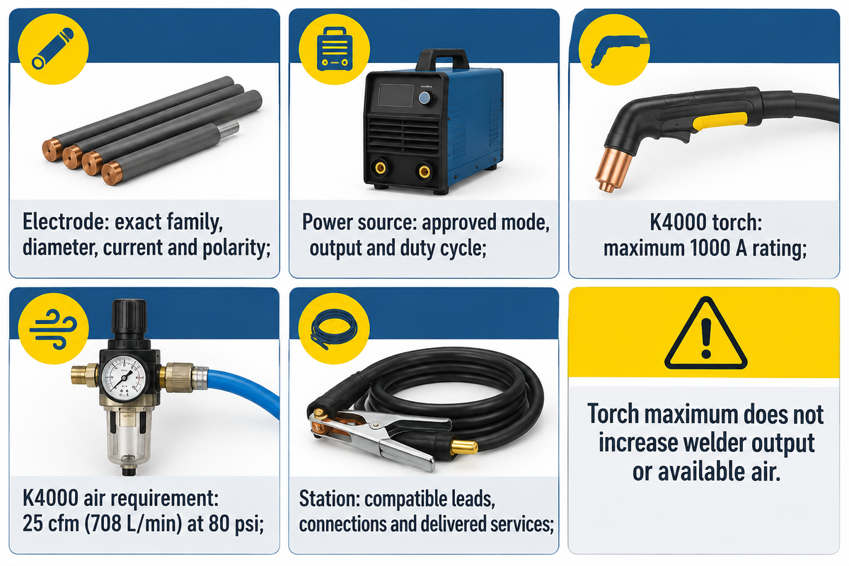
Match output and operating mode to the electrode first, then establish the torch and air requirements. Keep each equipment interface on the same purchase record.
What size welder do you need for arc gouging?
For Rockmount’s 1/8-inch Electra AAA, the welder has to provide 225 A as recommended, using AC or DCEN, with sufficient duty cycle for the specified work. No one welder accommodates all gouges. Start with the electrode’s current requirement, then use the machine manual to establish supported electrode sizes, setup and sustained capability.
Miller’s equipment guidance points to the source spec or owner’s manual and the electrode manufacturer’s amperage ratings. Its discussion also permits constant-voltage gouging with groove-shape tradeoffs and explains typical preference for constant-current arc behavior. A blanket “all CV machines are no good” rule would overlook that distinction.
Consumable-to-Utility Map
A Consumable to Utility Map links the selected removal method to the equipment and delivered services required to use it.
| Match point | Evidence to put on the job record | Decision owner |
|---|---|---|
| Electrode | Exact family, diameter, current and polarity instructions | Welding engineer / procurement |
| Power source | Approved gouging mode, usable output and duty cycle from its manual | Welding engineer / plant |
| Torch and air | K4000 example: maximum 1000 A; 80 psi; 25 cfm (708 L/min) | Plant / maintenance |
| Whole station | Compatible leads, connections and hose arrangement; delivered services during operation | Qualified equipment personnel |
If the existing welder supports the chosen electrode, obtain an itemized quote for the compatible torch/cable assembly, air hose and connections, and any shortfall in delivered air. Price any job prep/inspection work as well. This separates reusable equipment from new purchases instead of assigning every workshop the same setup price.
The K4000 numbers are from ESAB/Arcair’s manufacturer comparison chart. Match the K4000 to an air supply delivering 25 cfm at 80 psi, and check the welder’s sustained output separately from the torch’s 1000 A maximum rating. Buying a higher-rated torch doesn’t increase the output of the existing stick welder or the air available at the work station.
Airless Rods, Carbon Arc, Plasma or Grinding
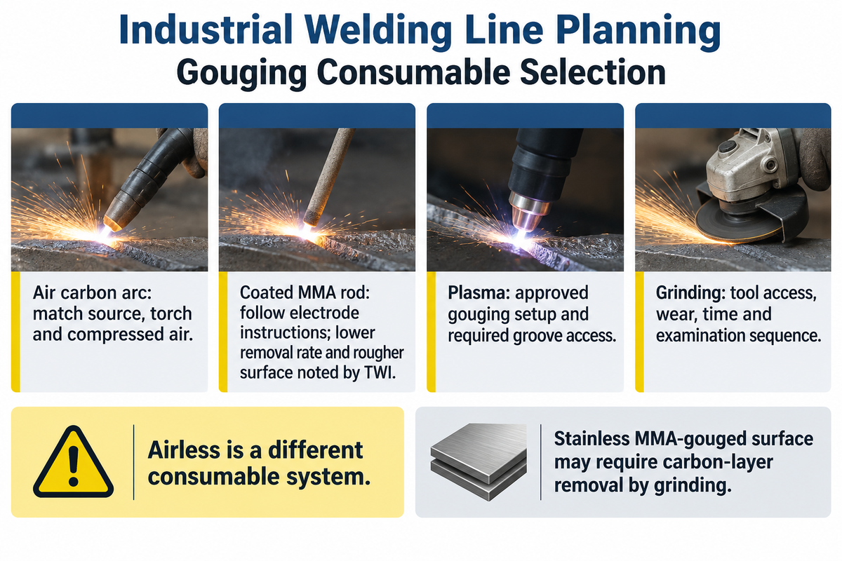
Can gouging rods work without air?
Purpose made flux-coated MMA gouging rods can remove metal without a dedicated compressed-air jet as the coating produces the ejecting gas stream. Air carbon-arc electrodes must have their own air supply and torch. The airless option is a different consumable system, not a means of running a carbon electrode without its clearing air.
| Method | Equipment question | Production tradeoff |
|---|---|---|
| Air carbon arc | Can the source, gouging torch and air system support the chosen carbon? | Coordinate metal clearing, surface condition and exposure controls. |
| Coated MMA gouging rod | Does the stick source match the specific electrode instructions? | TWI describes lower removal rates and a rougher surface than alternative gouging methods. |
| Plasma gouging | Does the plasma system have the approved gouging setup and consumables? | Match access and groove geometry to the second-side welding task. |
| Grinding | Does the selected tool reach the required profile? | Include abrasive wear, preparation time and the examination sequence in the job plan. |
Airless doesn’t mean cleanup-free for every material. TWI’s MMA guidance identifies a carbon-enriched surface on stainless steel that requires grinding. Compare total preparation work before choosing the cheaper consumable. Neither a TIG filler nor a MIG wire becomes a gouging product through a change of name.
Plan Exposure Controls Before Gouging
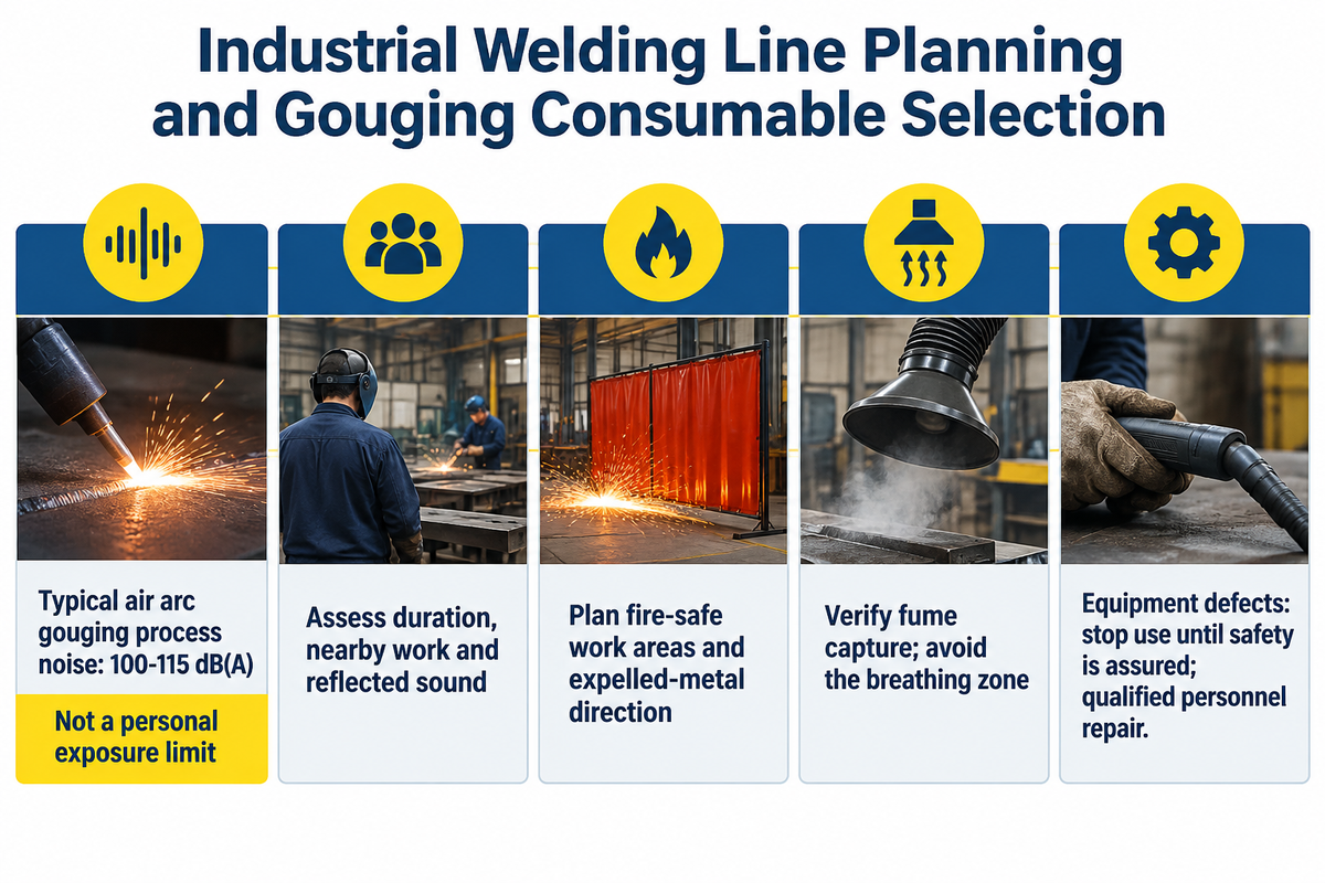
Hot metal, arc radiation, fume, electrical equipment and noise belong in the station plan before the first burn. The UK Health and Safety Executive lists typical air arc gouging noise at 100–115 dB(A). This is a process-level range, not a personal exposure limit; duration, nearby work and reflected sound affect exposure.
“Cutting or welding shall be permitted only in areas that are or have been made fire safe.”
The site assessment should address the direction of expelled metal, combustible materials, other workers, arc screening and fume capture. OSHA’s ventilation guidance explains source capture and the need to verify deficiencies by measurement. Positioning extraction so contaminants pass through the operator’s breathing zone defeats its purpose.
Use the applicable local hot-work and exposure rules, and qualified personnel for equipment checks. Under OSHA’s US general-industry equipment rule, defects are reported and use stops until safety is assured; qualified personnel perform repairs. Arc-air equipment must retain its specified air supply: oxygen-fed flame cutting torches belong to a different process.
Inspect the Groove Before Rewelding
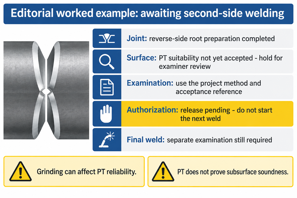
Release the prepared root against the job’s specified geometry, surface condition and examination requirements before closing the joint with the next weld. Record what was examined, the applicable acceptance reference and who authorized the next operation. A visibly open groove is the beginning of that check, not the entire inspection record.
ISO 17635:2025 addresses selection of weld nondestructive testing methods and evaluation of results using factors such as material, thickness, welding process and testing extent. Its quality levels and NDT acceptance levels are not interchangeable labels for every indication. The project inspection plan must identify the applicable method and criteria.
Surface preparation can change what penetrant testing can find. ASNT explains that grinding and other mechanical operations can smear metal over surface openings, reducing the reliability of a later penetrant examination. Agree the preparation and examination sequence with the responsible examiner, using the applicable procedure. Any further processing needed to produce a suitable test surface belongs in that procedure.
Groove Release Record
A Groove Release Record documents the preparation, examination basis and authorization needed to hand a prepared joint to the next welder.
| Record field | Example entry | Release consequence |
|---|---|---|
| Joint and operation | Repair groove; reverse-side root preparation completed | Match the joint to the approved repair instruction. |
| Prepared surface | Mechanical dressing recorded; PT surface suitability not yet accepted | Hold for examiner’s preparation review. |
| Examination and criteria | Required method and acceptance reference entered from the project inspection plan | Evaluate and record the result against that reference. |
| Authorization | Responsible examiner’s release pending | Do not start the next weld while the hold remains open. |
| Final weld | Separate completed-weld examination stage retained | Groove release does not replace final-weld acceptance. |
ASNT’s method overview limits PT to discontinuities open to the surface of suitable nonporous materials. A clean appearance and an absence of PT indications can’t establish that subsurface material is sound.
Troubleshoot Deposits and an Uneven Groove
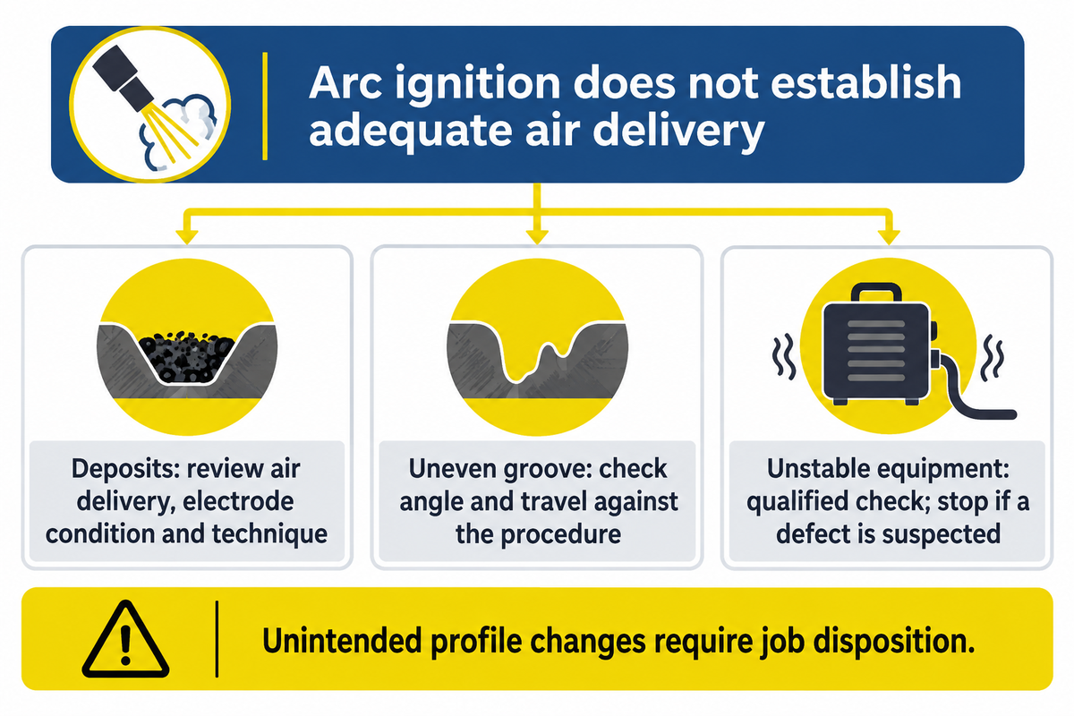
If metal remains in the groove, verify the metal-clearing function alongside the arc. For air carbon-arc gouging, an arc that starts does not establish adequate air delivery to remove molten metal. TWI associates carbon pickup with inadequate airflow or poor technique, so the symptom should trigger a review of the process conditions rather than an immediate increase in current.
- Deposits or suspected contamination: review air delivery, electrode condition and technique against the operating instructions; identify the required dressing before rewelding.
- Uneven depth or an unwanted hole: check control of the electrode angle and travel against the procedure before removing more sound material.
- Unstable operation: have qualified personnel check the source setup, connections and selected consumable. Stop if an equipment defect is suspected.
Remove slag and other unwanted deposits before rewelding according to the preparation procedure; leaving material in the groove defeats the intended clean welding surface. For a carbon steel repair application, the quality team should distinguish a surface cleanup task from excavation that has exceeded the intended joint profile. A larger gouge impacts the welding job.
An unintended profile change needs to be considered as a job disposition issue and not glossed over beneath further weld metal.
Fit the Gouging Station Around the Welding Line
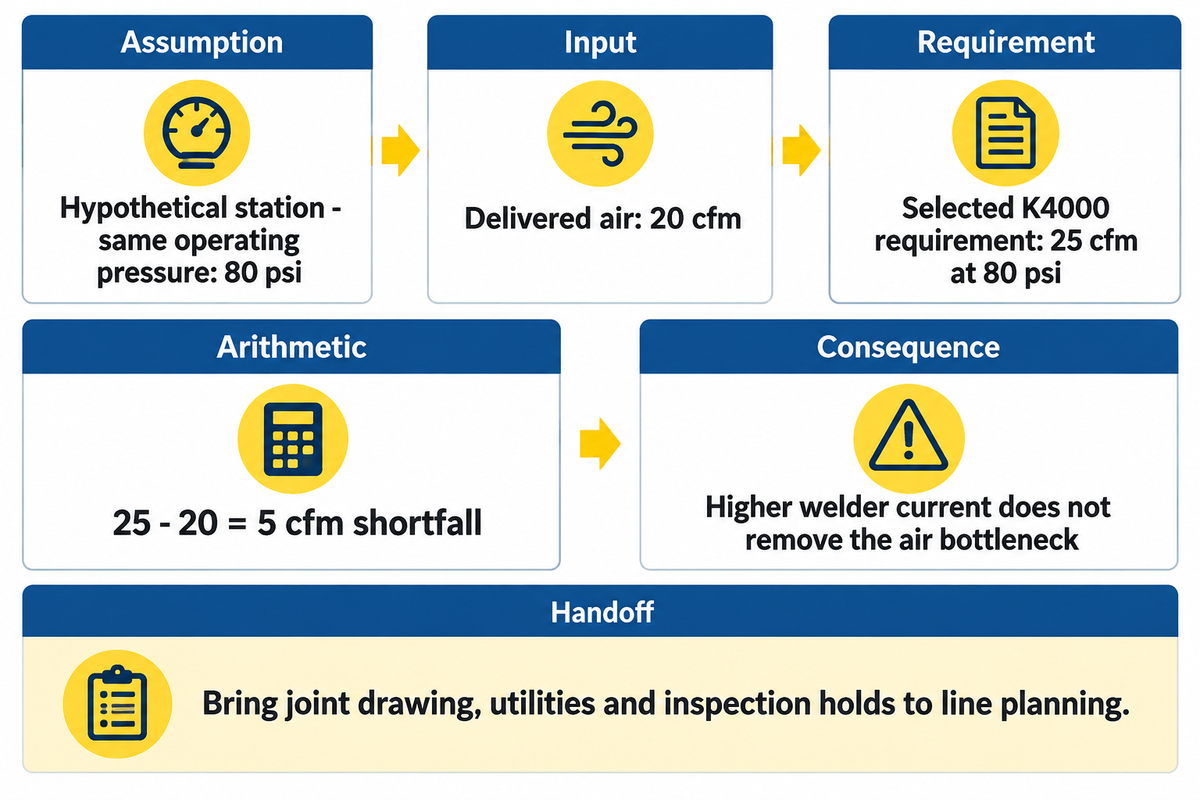
Consider a hypothetical station delivering 20 cfm at 80 psi when its selected K4000 torch calls for 25 cfm at 80 psi . The air supply is short by 5 cfm , so the station isn’t ready on that basis. Buying just a higher current welder doesn’t eliminate that bottleneck.
Station placement also affects nearby inspection and handling crews. Include surrounding work, duration and reflected sound in the site’s noise assessment. Keep the groove examination hold accessible within the production sequence.
Zhouxiang’s h beam welding line will move assembly, welding, turning and straightening into your fabrication discussion. For your line project, provide the joint drawing, planned removal task, available utilities and inspection hold points to your equipment discussion. The procurement team can then differentiate the consumables order, station needs and line integration scope, while the finance group considers the actual remaining equipment work.
Frequently Asked Questions
What is gouging welding?
Gouging is metal removal used during weld preparation or repair. The arc melts the workpiece and an air or process-generated gas stream clears the molten metal. Back-gouging applies that removal to the reverse side of a joint before further welding. Unlike filler deposition, its immediate result is an excavated groove or prepared surface.
Can you carbon arc gouge with AC?
Yes, with an AC-designated carbon electrode and a compatible power source and torch setup. ABIARC, for example, lists separate AC and DC pointed-electrode families. Select from the applicable product instructions rather than taking a DC carbon and copying a setting from a coated airless rod. For example, its 6.5 × 305 mm AC entry lists 350 A; the same nominal DC size is listed at 400 A.
Do you just run compressed air into the stinger?
No. Air carbon-arc gouging uses a purpose-built torch that holds the carbon electrode and directs the air jet at the removal zone. An ordinary electrode holder doesn’t acquire that function by adding an air hose. Use the manufacturer’s specified torch, connections and air arrangement, with qualified personnel checking compatibility. The separate power-source and air requirements still need to be met before operation.
Must the groove be ground before rewelding?
MMA gouging on stainless steel requires removal of the carbon-enriched surface described by TWI; preparation for other materials follows the approved repair sequence. TWI identifies carbon-enriched layers and material conditions that need dressing; airless rod marketing shouldn’t override that requirement. Equally, grinding isn’t a complete examination plan. ASNT describes how mechanical preparation can affect surface openings and subsequent PT reliability. Put the preparation method and any required further processing into the examination procedure, then evaluate the groove using the project criteria. The recorded preparation should identify how the groove was made suitable for its examination.
What must be inspected before the opposite side is welded?
Check the identified joint, the prepared root and groove geometry, the surface condition and the examination results required by the project inspection plan. Record the acceptance reference and release authority before the next welding operation. The operator’s completion of excavation and the examiner’s acceptance are different entries: both matter when the job has a hold point. Select any additional examination for the material and defect location being assessed. Select the test for the defect location and material specified in the inspection plan. Where surface preparation has changed the condition needed by the selected method, resolve that condition before interpreting the examination. Retain the final-weld inspection stage as a separate requirement after second-side welding. This keeps a useful production record of what was actually accepted, by whom, and at which stage.
Send the joint drawing, beam range and intended welding sequence when discussing the line layout. Include the gouging and inspection stages where the specified joint needs them, so utility and handling requirements enter the proposal early.
Technical basis: this guide combines named product instructions, welding guidance and published inspection-method information. The utility calculation and Groove Release Record are editorial examples, rather than reports of work performed by Zhouxiang. Job execution follows the applicable approved procedures and site requirements.
References & Sources
- TWI: Air carbon arc gouging; Manual metal arc gouging.
- Rockmount: Electra AAA settings. ABICOR BINZEL: ABIARC electrode tables.
- Arcair: Manual gouging torch comparison chart. Miller: Seven gouging equipment questions.
- AWS: Plate-girder fillet and groove connections. Hypertherm: Plasma back gouging.
- ISO: ISO 17635:2025 catalogue and scope. ASNT: PT method overview; PT preparation limitations.
- US OSHA: 1910.252; 1910.254; Ventilation guidance. UK HSE: Welding health risks and process noise.