Structure: Rolled tubular steel tower shell.
Shop work unit: A finished transport section.
Main joints: Longitudinal seams, circumferential seams and flange welds.
Planning basis: Section geometry, accepted output and station occupancy.
A wind tower starts as flat steel plate and leaves the factory as finished sections ready for the installation sequence. Between those points, the wind tower manufacturing process links cutting, forming, welding, inspection and finishing. Every operation must produce a workpiece ready for the next station, one that it’s prepared to accept.
That handoff becomes expensive when a can loses its material identity, a flange needs correction after welding, or completed steelwork waits outside an occupied coating bay. A production plan needs a record chain and a compatible workpiece range at every station, alongside the machinery list.
The wind tower manufacturing process turns checked steel plate into rolled cans, welds those cans into flanged sections, then completes inspection, surface protection, outfitting and dispatch. This sequence covers conventional tubular steel towers.
- Only when the remaining stations can take the additional work will a faster welding station increase finished output.
- A can is a rolled shell unit; a transport section has linked cans and section-end interfaces.
- Shop welds connect the steelwork. Bolted flanges commonly connect the completed sections at the wind turbine site.
- The scope of inspection, joint acceptance and coating requirements should be documented in the project documents before production starts.
How the Wind Tower Manufacturing Process Fits Together
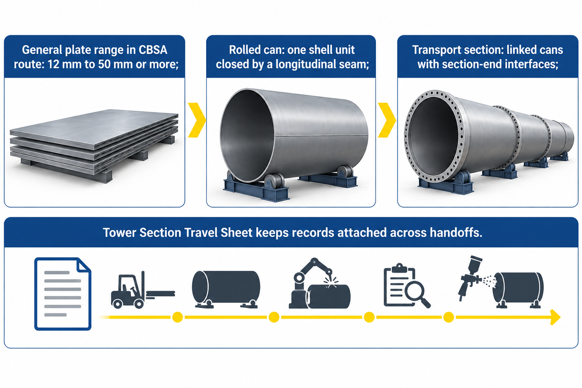
Normal wind tower fabrication progresses from prepared plates to rolled cans, constructed sections and completed transportation units. The section sketch dictates the way those units join together. Using the same definitions across purchasing, production and inspection prevents a quotation in cans per shift from being mistaken for a finished-section output commitment.
The Canadian Border Services Agency’s 2023 manufacturing description follows this rolled-and-welded route. It describes general plate thicknesses of 12 mm to 50 mm or more, selected for the turbine design and location in the tower. That range illustrates why a single nominal plate thickness is an inadequate machine specification.
The tower consists of a load-bearing shell supporting the nacelle at the top of the tower. Sections are manufactured separately and transported to the site for assembly. The production process for a wind turbine tower is thus associated with factory work and the intended bolted connections at the assembly site.
What is the difference between a tower can and a tower section?
A can is one cylindrical or conical shell unit closed by a longitudinal seam. Several cans joined around their circumferences form a transport section. Several sections are then used to assemble a complete wind turbine tower.
Can count, section count and tower count are each measures of differing quantities of manufacturing work.
Use the Tower Section Travel Sheet as a suggested record structure. Follow the completed entries to see what should stay attached to the workpiece as it’s forming; what records and signoffs are required are specified by the factory’s approved procedures.
| Handoff | Record to carry forward | Who uses it next |
|---|---|---|
| Plate receipt | Material certificate reference, plate identity and drawing allocation | Material control and cutting |
| Cut blank | Blank identity, can number and cutting revision | Forming team |
| Prepared edge | Joint designation and specified bevel arrangement | Fit-up and welding |
| Rolled shell | Can identity and geometry-check result | Long-seam station |
| Closed can | Seam identity, welding procedure reference and required examination status | Section assembly |
| Joined cans | Section identity, joint map and circumferential weld records | Dimensional inspection |
| Flanged section | Flange identities, orientation and measured interface geometry | Quality team |
| Released steelwork | Completed hold points and closed repair records | Surface preparation |
| Coated section | Coating system, application checks and cure status | Outfitting team |
| Finished section | Final configuration, marking and dispatch dossier | Logistics and customer |
Steel Plate Identification, Cutting and Edge Preparation
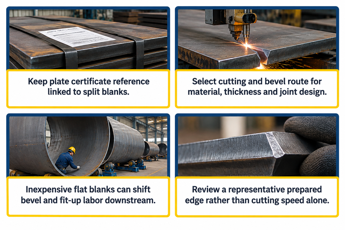
Plate preparation provides the blank shape and joint edges to the rolling and welding stations. The process starts with material distribution and drawing revision, then continues through cutting and the required bevel preparation. A well-equipped welding station still loses time when the incoming blank needs edge correction or re-identification.
Keep the plate certificate reference associated with the cut pieces in the proposed travel sheet. This is a practical record recommendation: a split plate should remain traceable to the material assigned to that section. Marking methods and mandatory documentation follow the purchaser’s quality requirements.
Plasma cutting and oxy-fuel cutting are included in the description of the CBSA process. Laser cutting or mechanical edge preparation may form part of another manufacturing method. Select the cutting machine and edge-preparation route for the specified material, steel plate thickness, blank size and joint design.
If a low cutting-equipment price appears attractive, it can be tempting to buy it without determining if you’ll receive the necessary bevel work. Cutting raw plate to a profile is only part of preparing it for joint welding. An inexpensive flat blank can shift machining, cleaning and fit-up labor into the next department.
Ask for a representative prepared edge as part of the equipment discussion, rather than comparing cutting speed alone.
Plate Rolling and Longitudinal Seam Welding
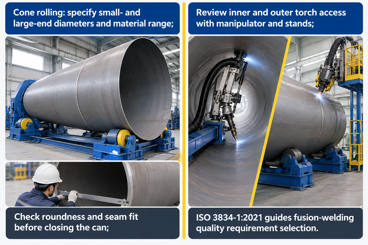
Plate rolling gives the blank a cylindrical or tapered shell, and longitudinal seam welding closes that shell into a can. These operations are related by geometry and joint preparation. The rolling machine must handle the actual plate width, material range and smallest required diameter, including the forming work needed near the plate ends.
For a tapered section, specify its small- and large-end diameters, developed blank, material range and required edge forming when asking for a cone-rolling configuration. The supplier should map that workpiece to forming and support capacity. A plate rolling machine rated for one material and width is a starting point for selection. This bending machine forms the tower wall, and the thickness of the steel affects its duty. In a Practical Machinist discussion about plate-roll capacity, users debated how material strength, workpiece width and bend diameter affect capacity. Compare the published rating with the required material strength, workpiece width and bend diameter; the discussion’s numerical rules disagree.
Check the roundness and seam fit against the fabrication documents before closing the can. After welding is completed, the specified dimensional and weld tests determine whether the can may proceed to section assembly. Re-forming and repairs must have unique routing if the result doesn’t meet project requirements.
Submerged arc welding is widely associated with long, repeated joints. The welding method and welding machine are selected through the joint procedure and production requirements. Different welding arrangements may be needed for shell seams and local attachments.
Column-and-boom manipulators place this welding device; stands and positioning equipment present the workpiece. Torch access to the inner side and outer side belongs in the layout review.
Connect the joint map to the applicable welding procedure, personnel qualification requirements and process records. Topics such as welding preheat require a procedure-based decision for the joint and material. The ISO 3834-1:2021 framework addresses selection of fusion-welding quality requirements across workshop and field manufacture.
Fit-Up, Circumferential Welds and Flange Attachment
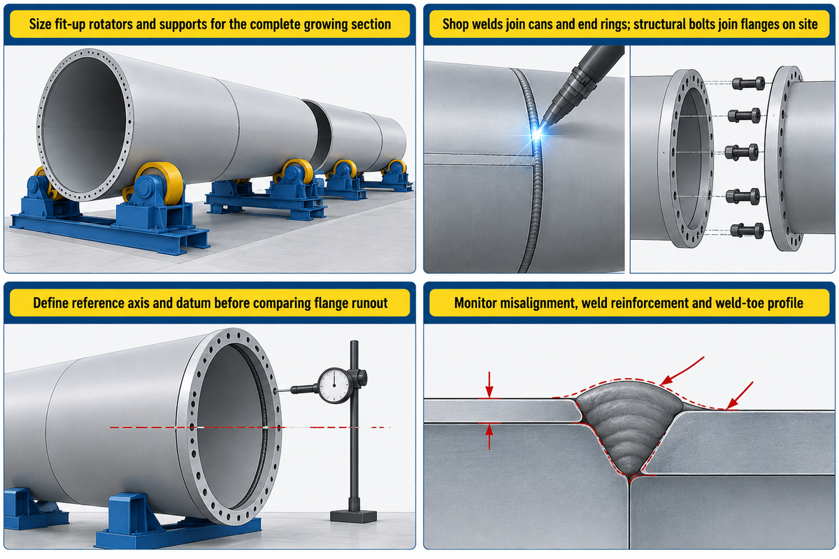
Fit-up aligns cans for circumferential welds and positions the flanges that will join the finished segments. The supports for a growing assembly change as the weight and space demands of the assembly alter. The production sequence must cover the complete section, including the final joint, instead of sizing the station around an individual empty can.
Hydraulic fit-up rotators provide adjustable support for alignment. Compare the support and movement with the section drawing and the joining sequence.
A large rated load alone leaves the placement of supports, workpiece contact and alignment range unresolved.
Are wind tower joints welded or bolted?
The interface connections both occur in the normal path; longitudinal and circumferential welds connect the shop-fabricated shells, and flange welds connect the section-end rings. During wind turbine installation, structural bolts connect the mating flanges. The approved tower design fixes the connection arrangement and the technical requirements for each interface.
Flange geometry deserves a separate inspection step. The European RINGMAN project’s final report examined how out-of-flatness affects a flange connection in its alternative fabricated-flange research. Flange out-of-flatness is a geometry concern, and the project drawing supplies the applicable manufacturing limits.
How is flange runout measured?
Flange runout is measured with respect to the reference axis and datum arrangement established for the section. The measurement plan details the support condition, instrument and locations to record. Specify the arrangement before comparing results, because measurements using different references do not answer the same geometry question for the finished steel tower.
Local weld geometry matters as well. A 2024 study of wind-tower butt-welded joints used fatigue tests, measured seam geometry and numerical analysis to examine fatigue resistance. Misalignment, weld reinforcement and the weld-toe profile therefore deserve process attention alongside the final examination results.
“Excessive weld cap reinforcement is also a concern.”
Inspection Before Surface Treatment
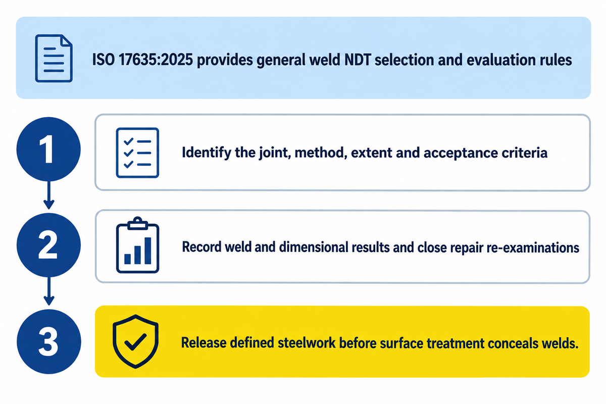
Inspection checks the specified weld condition, dimensions and interfaces before surface treatment conceals the steelwork. The inspection plan assigns each examination to a manufacturing stage, with an acceptance basis and a record that releases the section. Repair and re-examination routes need to be planned with the same workpiece identification.
ISO 17635:2025, Edition 4 published in April 2025, provides general rules for selecting non-destructive testing methods and evaluating welds. Selection considers quality requirements, material, weld thickness, welding process and testing extent. Its acceptance levels are not a direct interpretation of ISO 5817 or ISO 10042 quality levels.
The inspection sheet should state what is inspected, the inspection method and extent, and the criteria for acceptance.
An order for ultrasonic or radiography examination does require those answers. A general inspection percentage for all wind tower projects would obscure the differences in each project.
- Identify the joint and the applicable inspection document.
- Record the required weld and dimensional results.
- Close repair findings and the associated re-examination.
- Release the defined steelwork before the relevant surface-treatment stage.
For quotation comparison, allocate responsibility for examination access, handling and hold-point attendance. An inspection service priced separately from the manufacturing line can still share the same supports and floor space.
Blasting, Coating and Internal Outfitting
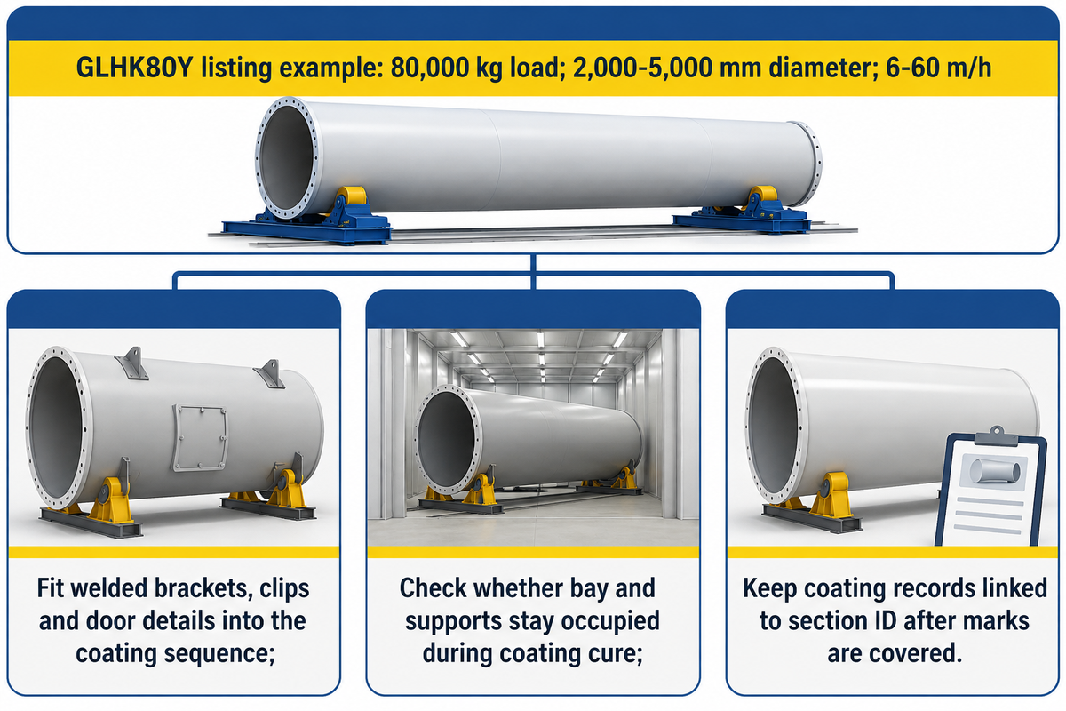
Surface preparation and coating protect the completed steelwork, while internal outfitting adds the components needed inside the tower. Welded brackets, clips and door details must fit the coating sequence. Mechanical and electrical installation then follows the approved assembly plan, including any protection and coating repair required around fitted items.
Zhouxiang’s published GLHK80Y blasting and painting rotator listing gives an 80,000 kg rated load, a 2,000–5,000 mm diameter range and a listed linear speed of 6–60 m/h. These are the movement and workpiece specifications of that coating-stage model; they’re separate from welding travel speed and finished-section output.
Plan the coating route around section entry, preparation, application, cure occupancy and exit. Ask whether the same bay or support equipment remains occupied while the coating cures.
Moving the part may free one resource, but introduce another handling operation.
The CBSA description includes outer and inner surface preparation, metallic coating, if any, and one or more paint coats. The protection system used defines the surface condition, application requirements and inspection requirements. Coating records should remain associated with the section identification once the original steel identification marks are no longer readily accessible.
From Finished Tower Section to Dispatch
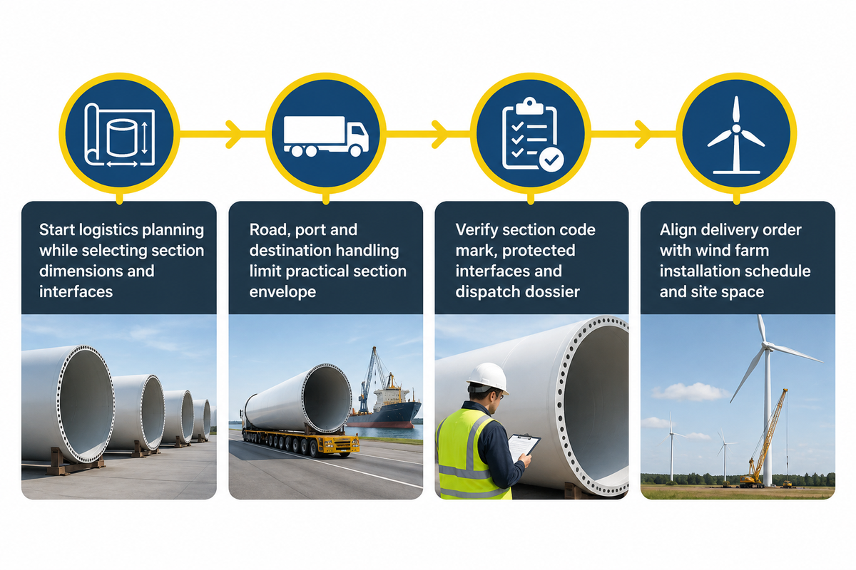
Once a section has been completed and the fabrication, coating, outfitting and final checks of the section are consistent with the agreed delivery configuration, it’s ready to be dispatched. The dispatch dossier links the physical section with its records. Logistics planning should start as the section dimensions and interfaces are being selected, as the factory exit is just one part of the route.
The U.S. Department of Energy’s manufacturing overview identifies transportation and logistics constraints that limit tower size and height. Road transport, port access and destination handling can change the practical section envelope for onshore or offshore wind projects.
Compare the delivery plan with the section code mark, final configuration, protected interfaces and transport documentation. Tower height by itself doesn’t specify a transport envelope for a large diameter section. Engineered lifting and support arrangements belong with the responsible project specialists.
Keep the delivery sequence aligned with the customer’s wind farm installation schedule and the receiving team’s available space.
What Limits Tower Manufacturing Throughput?
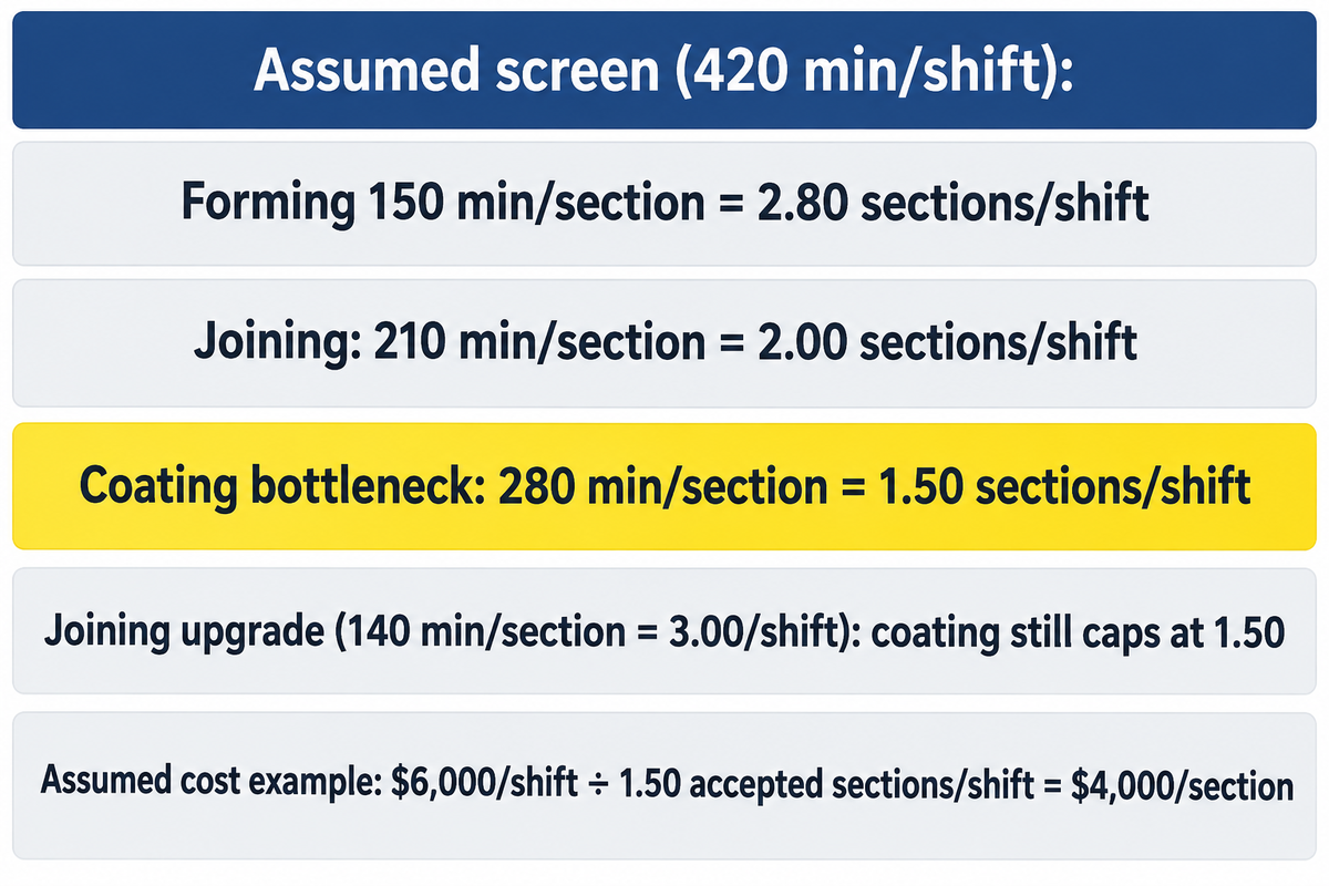
The resource with the lowest accepted-section capacity limits throughput; coating is the limiting station in the assumed example below. Rolling speed, weld deposition and coating movement are different activities. Compare station occupancy for the same section family, then include inspection holds, handling conflicts, repairs and the space occupied by work waiting for the next operation.
Linde’s October 2026 productivity discussion explains how fit-up, cleanup and upstream delays can absorb gains from faster welding. NIST’s product-mix research also shows that bottlenecks and throughput can change with the manufacturing mix, although its application is automotive assembly.
Assumed example: each station has 420 productive min/shift, with one equivalent station for each operation and the same section mix. Occupied times are 150 min/section for forming, 210 min/section for joining and 280 min/section for coating. Dividing available time by occupied time gives preliminary station upper bounds.
| Operation | Occupied time | 420 min/shift ÷ occupied time | Planning implication |
|---|---|---|---|
| Forming | 150 min/section | 2.80 sections/shift | Capacity remains above the coating screen |
| Joining | 210 min/section | 2.00 sections/shift | Some spare capacity relative to coating |
| Coating | 280 min/section | 1.50 sections/shift | Lowest preliminary station output |
| Joining upgrade | 140 min/section | 3.00 sections/shift | Coating still limits the screen to 1.50 sections/shift |
These quotients are steady-state screening bounds. Shared cranes, blocking, starvation, changing product mix and accepted yield require a fuller schedule; parallel coating bays also need a different resource model. An MIT serial-line teaching example demonstrates why adequate independent machine rates can still produce lower combined output when failures propagate between stations.
For an assumed conversion-cost example, $6,000/shift divided by 1.50 accepted sections/shift yields $4,000 per accepted section. For this separate cost example, 1.50 accepted sections/shift is an assumed realized output. Use measured accepted output in a factory cost estimate; the station screening bounds alone cannot establish that output.
Plate, bought flanges and freight aren’t included here. If the joining upgrade adds cost while finished output stays unchanged, it raises this conversion cost per section unless another saving offsets the increase.
Measure coating occupancy and crane waiting before approving a welding-only capacity investment. Record repair time against the joint that caused it, so the production manager and quality lead can distinguish extra demand from avoidable rework.
Matching Wind Tower Equipment to the Production Plan
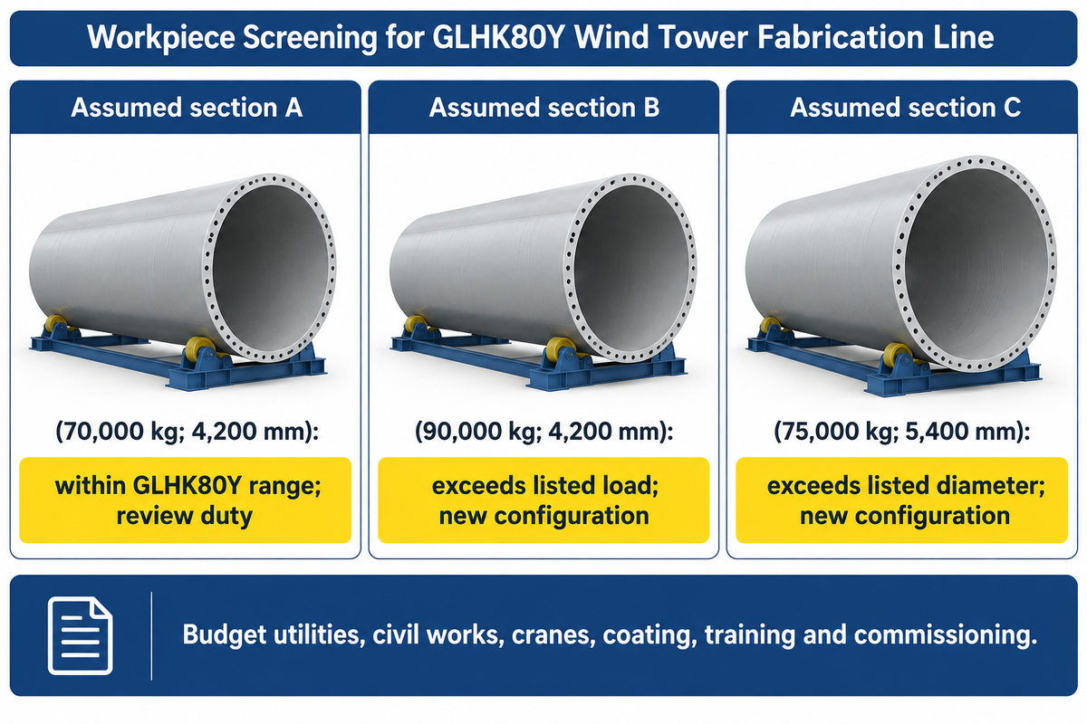
Match equipment to a defined family of cans and completed sections, then test the limiting workpieces at every station. Diameter, mass and plate thickness impose differing requirements. A machine package for building a tower needs compatible forming, support, welding and finishing arrangements, with agreed responsibilities for transfers and inspection access.
The Station Envelope Match given below takes the GLHK80Y listing as one supplier example and presumes the inquiry workpieces. It is a preliminary mass-and-diameter screen. Support spacing, load distribution, contact conditions, drive duty and process suitability still require an engineered equipment review.
| Comparison item | Input or condition | Next decision |
|---|---|---|
| Assumed section A | 70,000 kg; 4,200 mm diameter | Within the listed mass/diameter range; proceed to support and duty review |
| Assumed section B | 90,000 kg; 4,200 mm diameter | Exceeds the listed load; request another configuration |
| Assumed section C | 75,000 kg; 5,400 mm diameter | Exceeds the listed diameter; request another configuration |
| Plate rolling | Material strength, plate width, thickness and forming diameter | Obtain the rating conditions for the forming machine |
| Can support | Initial can geometry and changing assembly mass | Define support positions through section growth |
| Joint access | Longitudinal and circumferential work, inside and outside | Check manipulator reach and workpiece presentation |
| Flange interface | Ring geometry and measurement reference | Include fixturing and dimensional checks |
| Inspection hold | Required access and resource occupancy | Assign equipment and attendance responsibility |
| Coating occupancy | Application, cure and transfer sequence | Compare bay capacity with incoming section rate |
| Dispatch interface | Finished geometry and delivery configuration | Check factory exit and the planned transport route |
Zhouxiang supplies cutting and welding equipment for steel structure manufacturing; a method for manufacturing lower heavy sections may demand different forming and support capacity from the upper tower work. For an equipment discussion, prepare the reference drawings, smallest and largest workpieces, joint processes, shift pattern and finishing route. Use the wind tower equipment page as the production-line starting point.
Keep the quotation milestones distinct: machine dispatch, installation and acceptance of the agreed trial sections. Ask for the utilities, civil works, cranes, coating facilities, training and commissioning exclusions in the same scope table. A lower machinery price is useful only when the omitted interfaces are budgeted and assigned.
Frequently Asked Questions
Which wind tower manufacturing process is best?
For conventional tubular steel towers, use the fabrication route defined for the shell material, geometry and connection design: cut and prepare plate, roll cans, weld sections, inspect, coat and fit out. Concrete, hybrid, spiral-welded and bolted-shell towers need different routes, so choose production equipment for the actual approved tower design.
Is wind tower manufacturing profitable?
Wind tower manufacturing is profitable when accepted-section revenue exceeds total delivered production cost at the factory’s realized utilization. Account for plate, flanges, labor, consumables, energy, inspection, coating, handling, repairs and overhead, then compare that total with contracted selling prices and realistic utilization. Match the forecast to the section family and factory schedule before committing capital to the equipment package.
Where are wind towers manufactured?
Wind towers are made in heavy-fabrication facilities serving regional wind power, wind energy and other renewable energy supply chains. A factory receives plate and components, fabricates transportable sections, finishes them and ships them for installation. Machinery suppliers can equip that factory without producing its towers, so distinguish the equipment supplier, tower fabricator and turbine manufacturer when comparing companies.
Where are doors and attachments welded?
Door frames and welded support attachments are fitted to the shell at the stages defined by the fabrication drawings. Welding and inspection normally need completion before the affected area receives its final coating; removable internals can be installed later.
What should a wind tower production-line quotation include?
A useful quotation identifies the workpiece range, reference section, output basis and equipment supplied at every station. It should distinguish plate preparation, rolling, fit-up, welding, handling, inspection and coating, then state utilities, layout, commissioning, training and exclusions. Compare the same accepted-section basis across offers, including waiting, curing and repair assumptions. Ask the supplier to demonstrate the limiting workpieces rather than only the largest rated load. Include crane duties, transfer routes and inspection responsibilities that control the release of finished sections.
Has the wind tower manufacturing process changed?
Yes, equipment integration and process monitoring have developed, while the manufacturing process of wind turbine towers made of steel retains forming, welding and finishing.
Why use a steel tubular tower for wind turbines?
A tubular steel tower provides a load-bearing shell for wind power generation while enclosing access and services. Fabrication in transportable sections allows factory rolling, welding and coating before field assembly. Its geometry, material and connection details are selected for the turbine and site loads. Concrete, lattice and hybrid towers are alternative structural systems. Each transport section also provides factory access for welding and surface treatment before delivery. The purchaser can inspect its joints and protective system at the manufacturing facility, with the section records accompanying the physical structure.
Plan the section family before choosing the line
Bring the can and finished-section drawings, target accepted output, inspection route and coating occupancy to the equipment discussion. Zhouxiang can discuss the cutting, welding and handling equipment scope around those inputs. Include the bottleneck record and the workpieces that challenge each station.
Scope: This educational guide combines public manufacturing descriptions, technical literature and Zhouxiang product information. Project drawings and approved procedures control fabrication and acceptance.
References & Sources
- CBSA, Wind towers final determination, 2023: manufacturing description, paragraphs 30–34.
- ISO 17635:2025: general rules for non-destructive testing of metallic welds.
- ISO 3834-1:2021: selection of fusion-welding quality requirements.
- Welding in the World, 2024 tower butt-weld fatigue study: experimental and numerical geometry evaluation.
- European Commission, RINGMAN final report, 2014: alternative flange research.
- Johansson and Wahlen, The Fabricator, September 2011: tower-welding consumables and joint geometry.
- DOE, Wind Manufacturing and Supply Chain: infrastructure and transport context.
- Denno and Alvian, NIST, 2018: product-mix-dependent throughput.
- MIT manufacturing-systems teaching example, 1996: serial-line rates and buffering.
- Linde Canada, October 2026: data-driven welding productivity.