Updated November 2026 · Industrial Robotic Arc Welding Cell Engineering and Integration Guide
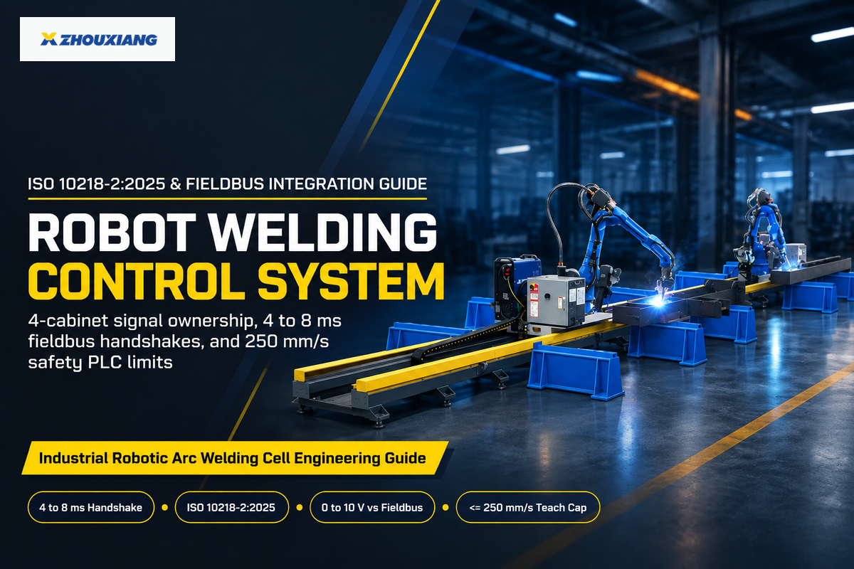
An industrial robot welding control system splits real-time execution across four hardware cabinets instead of one central computer. The six-axis robot controller computes path interpolation every 1 to 8 ms. A dedicated welding power source regulates arc voltage and welding current at microsecond inverter speeds. Meanwhile, a dual-channel safety PLC monitors cell gates under ISO 10218-2:2025 and ANSI/A3 R15.06-2025. A fourth drive rotates the workpiece on welding positioners.
First-time robotic automation buyers often assume the arm cabinet directly drives amperage, light curtains, and turntables. Undisciplined engineering practices, like using unshielded analog leads or single channel relays, cause commissioning delays. High welding consistency and strong productivity start with mapping signal ownership and pinouts across every cabinet before ordering equipment.
Quick Specs: Robot Welding Control System Timing, Interfaces & Safety Thresholds
| Four Hardware Control Layers | 6-axis robot controller, inverter welding power source, dual-channel safety PLC, and positioner / cell PLC |
| Inter-Controller Handshake Budget | 4 to 8 ms cyclic fieldbus exchange; 0.5 to 1.5 s Arc-Established start-hold timeout |
| Power-Source Interface Tiers | Hardwired 24 V discrete + analog voltage channels vs. EtherNet/IP, PROFINET, EtherCAT, or OEM weld bus |
| Manual Teach-Pendant Speed Cap | ≤ 250 mm/s (10 in./s) with 3-position enabling switch (OSHA OTM Section IV Ch. 4 & ISO 10218-1:2025) |
| Arc Electrical & Calibration Rules | ≤ 100 V automatic open-circuit cap & bonded return (OSHA 29 CFR 1910.254); calibration per ISO 17662:2025 |
| 2026 Cell Budget & Build Windows | $15,000 to $80,000 factory-direct workstations (30 to 45 days, Zhouxiang) vs. $100,000 to $250,000 US turnkey cells (Relling 2026) |
What Is a Robot Welding Control System? 4-Subsystem Signal Ownership
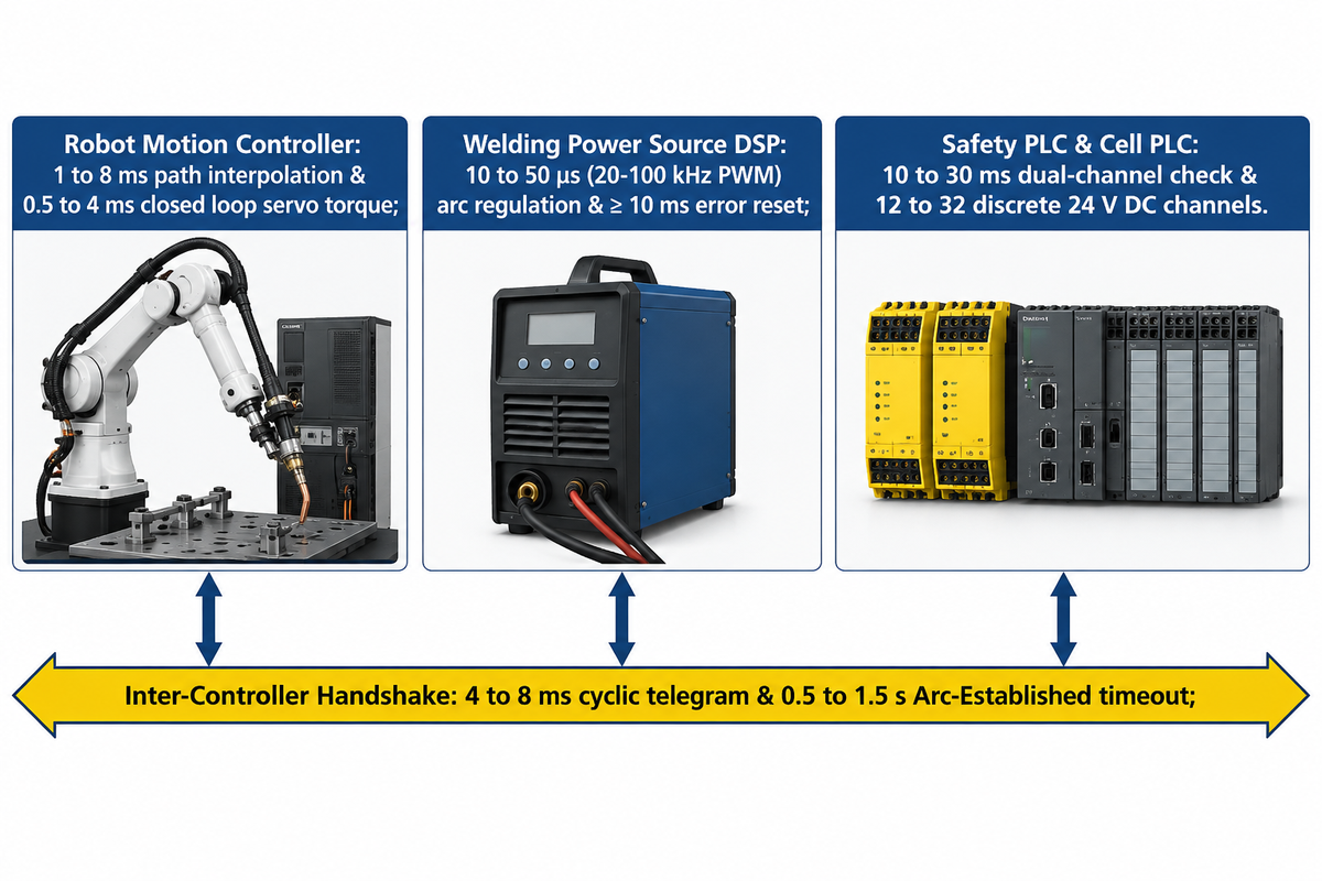
A robotic welding system divides execution across four control domains: microsecond inverter arc regulation, 1 to 8 ms robot and coordinated positioner path interpolation loops, 10 to 30 ms safety-PLC dual-channel checks, and 50 to 250 ms cell-PLC auxiliary sequences. Inter controller handshakes occur within a 4 to 8 ms budget, and a timeout is set for 0.5 to 1.5 seconds to declare arc established.
Consider a robotic weld cell more like a surgical team rather than a single surgeon. The robot controller routes the welding torch along a 3-dimensional weld path. Meanwhile, the inverter, acting as a power source, enables metal droplet transfer faster than the quickest mechanical arm joint can respond. Per the OSHA Technical Manual Section IV, Chapter 4, industrial control systems link the manipulator, teach pendant, end-effector, and peripheral equipment. Unsynchronized live inputs from peripheral controllers can lead to unanticipated robot motion when signal ownership is unclear.
All automated welding passes go through a six-step handshake to control the welding sequence. First, the arm parks the wire tip at the start point and triggers gas pre-flow for 0.2 to 0.5 s. In the second step, the Weld controller enables the start output, while holding the arm motionless. Third, the welder ignites the arc and returns the Arc Established status bit. Missing the confirmation, beyond 0.5 to 1.5 s, causes an arc-start fault and aborts the process. Fourth, the arm accelerates to programmed welding speed along the joint. In the fifth step, at the seam end, the controller runs crater fill to alleviate shrinkage cracking. Sixth, the inverter fires a millisecond burnback pulse and wire stick-check before the torch retracts to a reaming station.
When configuring their first robotic welder, clients typically omit auxiliary station wiring from their electrical schematics. Pneumatic fixture clamps, part-present proximity sensors, fume extract dampers, and nozzle reamers require 12 to 32 discrete 24 V DC channels. Off-loading those tasks to a compact cell PLC allows the robot CPU to focus on path synchronization.
What Type of Control System Is Used to Control the Robotic Welding Process?
Industrial robotic welding consists of a hierarchical, closed-loop distributed control system. It integrates a six-axis servo motion controller, a high-frequency inverter power-source regulator, and a dual-channel safety PLC. Motion loops are updated in milliseconds and inverter current loops are switched in microseconds.
A distributed control system is used to address many types of welding and a wide variety of welding processes. This same controller hierarchy is used for metal arc welding, tig welding, plasma welding, robotic plasma cutting, resistance welding, and spot and laser welding. In a laser welding or beam welding cell, a fiber laser replaces the arc inverter while keeping the same 4 to 8 ms motion handshake.
| Signal Cluster | Originating Cabinet | Receiving Hardware | Typical Signal Medium | Cycle / Timeout Window |
|---|---|---|---|---|
| 1. 6-Axis Joint Servo Torque & Encoder | Robot Motion Controller | Arm AC Servo Amplifiers & Encoders | Proprietary high-speed servo bus | 0.5 to 4 ms closed loop |
| 2. Weld Start & Job / Setpoint Command | Robot Motion Controller | Welding Power Source Interface | 24 V DC + 0–10 V analog or Fieldbus | 4 to 8 ms cyclic telegram |
| 3. Arc Established & Main Current Status | Welding Power Source | Robot Motion Controller | 24 V digital input or Fieldbus bit | 0.5 to 1.5 s motion-hold gate |
| 4. Inverter PWM Waveform & Wire Feed | Welding Power Source DSP | IGBT Bridge & 4-Roll Wire Feeder | Internal inverter bus / LocalNet | 10 to 50 μs (20–100 kHz PWM) |
| 5. Source Error Reset & Wire Stick Check | Robot Motion Controller | Welding Power Source | 24 V pulse or Fieldbus reset bit | ≥ 10 ms reset pulse (Fronius spec) |
| 6. E-Stop, Gate Interlock & Light Curtain | Safety PLC / Safety Relay | Robot STO & Welder Safety Contactor | Dual-channel 24 V OSSD or CIP/PROFIsafe | 10 to 30 ms dual-channel check |
| 7. Coordinated 7th/8th Positioner Axes | Robot Multi-Group Solver | Auxiliary Servo Drive & Gearhead | OEM servo bus / CIP Motion / EtherCAT | 1 to 4 ms kinematic sync |
| 8. Seam-Tracking Offset Vector | 2D/3D Laser Camera or TAST Board | Robot Path Correction Register | Industrial Ethernet / Sensor Ethernet | 4 to 20 ms real-time path shift |
| 9. Torch Reamer, Wire Cutter & Clamps | Cell PLC (or Robot Aux I/O) | Solenoid Valves & Reamer Station | Discrete 24 V DC sinking/sourcing I/O | 50 to 250 ms station sequence |
Welding Power Source Interfaces: Hardwired 0–10V Analog vs. Digital Fieldbus
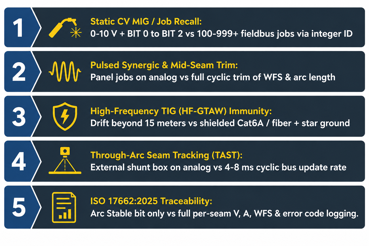
For basic function, wire in 24 V discrete inputs and 0 to 10 V analog outputs for constant voltage MIG set points and binary job recall. Choose a 4 to 8 ms digital fieldbus instead for advanced welding with 100 to 999+ pulsed synergic schedules, real-time Through-Arc Seam Tracking, and per-seam weld data logging.
It’s a common myth in the shop that hardwired analog interfaces can only run one static schedule. However, primary OEM hardware manuals disprove this myth. Fronius ROB 4000 and ROB 5000 interface documentation disproves this myth: the basic ROB 4000 sends 0 to 10 V analog welding current commands while keeping mode selection on the welder panel. The ROB 5000 has additional features such as discrete binary bits (BIT 0 to BIT 2), and robot-triggered Job mode recall. It also features touch sensing, process active feedback, and a 10 ms source error reset pulse without Ethernet cabling.
In processes with tight tolerances such as pulsed synergic trim and seam tracking, digital fieldbuses are critical. Digital fieldbus links also support automated weld quality logs. Engineers auditing robotic welding parameter windows and setpoint traceability read actual voltage, current, and wire-feed speed over cyclic bus words. North American plants predominantly use EtherNet/IP or DeviceNet. European plants predominantly use PROFINET or EtherCAT. OEM weld buses such as ArcLink XT load menus straight to the robot pendant.
Long cable lengths and high frequency arc starts create a second dividing line. Beyond 15 meters of gantry cable tracks, low voltage analog leads start to suffer resistive drop and create inequality in the wire feed rate. AC GTAW high-frequency arc starts radiate radio-frequency noise into unprotected analog cables. That interference can destroy solid-state controller boards without star building grounds, calibrated spark gaps, and shielded fieldbus lines. Matching RJ-45 jacks on a robot arm and a welding machine still block communication when the protocols differ. A PROFINET adapter can’t talk to an EtherNet/IP scanner, unless a gateway or option card is used.
| Process Signal Requirement | 24 V Discrete + 0–10 V Analog | Standard Fieldbus (EtherNet/IP, PROFINET, DeviceNet) | Native OEM Welder Bus (e.g., ArcLink XT) |
|---|---|---|---|
| 1. Static CV MIG / Basic Job Recall | Sufficient (0–10 V setpoints + binary Job bits) | Supported (100–999+ stored jobs via integer ID) | Supported with full pendant waveform graphics |
| 2. Pulsed Synergic & Mid-Seam Trim | Limited to pre-saved welder panel jobs | Full cyclic trim of WFS, arc length & inductance | Real-time waveform & pulse-mode switching |
| 3. High-Frequency TIG (HF-GTAW) Immunity | High EMI drift risk on unshielded 0–10 V leads | High immunity with shielded Cat6A / fiber + star ground | Engineered shielded cable assembly + isolated transceiver |
| 4. Through-Arc Seam Tracking (TAST) | Requires external current-shunt sensor box | Supported within 4–8 ms cyclic bus update rate | Native deterministic arc-current feedback loop |
| 5. ISO 17662:2025 / Weld Data Traceability | Pass/fail Arc Stable bit only without external logger | Logs actual V, A, WFS, gas fault & error codes per seam | Full production monitoring & weld-score logging |
Safety PLC Architecture and Cell Interlocks Under ISO 10218-2
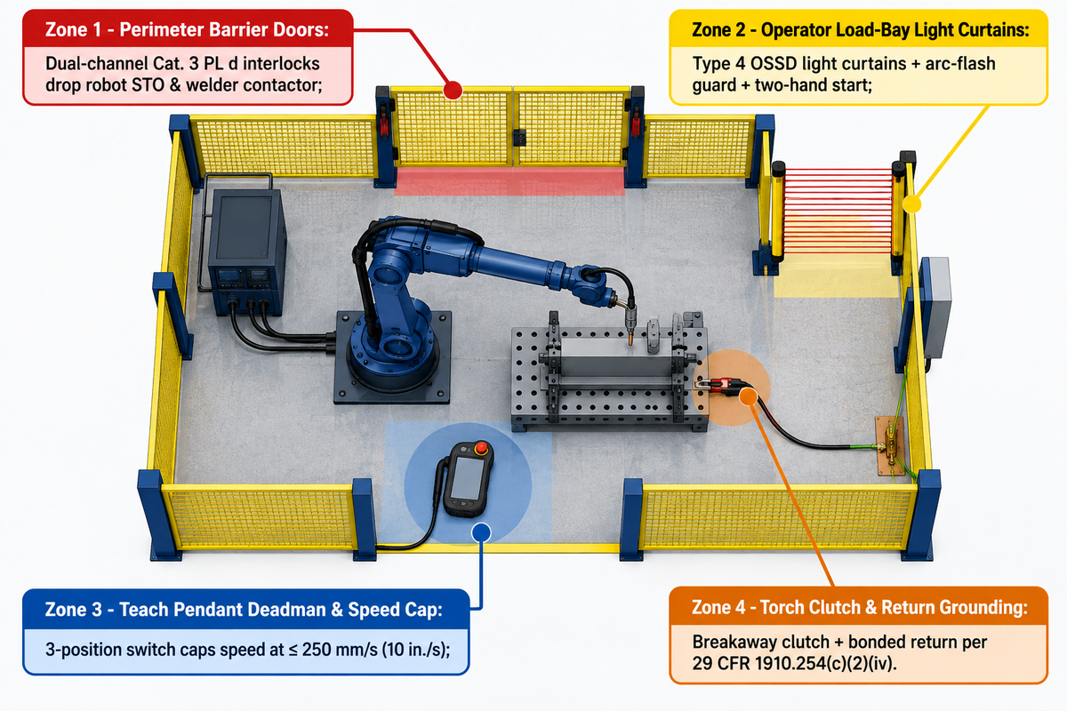
Under ISO 10218-1/2:2025 and ANSI/A3 R15.06-2025, robotic weld cells require dual-channel safety circuits (ISO 13849-1 Category 3, PL d) and a manual teach speed cap of 250 mm/s (10 in./s) or less. Defective welding gear must also be locked out immediately under OSHA 29 CFR 1910.254(d)(9). Standard PLC outputs never qualify for life-safety stops.
“For this reason, robot speeds should be placed at a reduced speed of 10 inches per second (250 mm/second) or less, on any part of the application during teaching to decrease the likelihood of contact and minimize the potential of injuries.”
Why do plant safety engineers reject standard PLC ladder logic on perimeter gates? One welded relay contact or shorted transistor inside a standard PLC silently defeats the stop circuit. Safety PLCs (running CIP Safety, PROFIsafe, or FailSafe over EtherCAT) cross-check two redundant channels using pulsed test signals. As outlined in The Fabricator’s robotic welding safeguarding guide, gate interlocks wire directly through safety contactors. Opening a cell door during welding work cuts power to both arm servos and welding power contactors.
Two 2025 safety findings reshape new robotic welding installations. Published in October 2025, the 403-page ANSI/A3 R15.06-2025 standard aligns US rules with ISO 10218-1:2025 and ISO 10218-2:2025. It regulates collaborative applications rather than treating any cobot arm as automatically safe around hot wire and arc flash. Meanwhile, a peer-reviewed reliability study in NIH PubMed Central (PMCID: PMC12595067) measured operator error rates on robotic welding stations. Poor HMI design and weak documentation pushed error probabilities from 13%–23% up to 28%–46%, confirming that training alone cannot replace hardware interlocks.
The 4-Zone Welding Cell Interlock Checklist
- Zone 1 — Perimeter Barrier Doors: Wire every maintenance gate with dual-channel interlock switches to drop robot Safe Torque Off (STO) and welder contactor power. Use a guard lock out if the coasting time is greater than the operator’s reach.
- Zone 2 – Operator Load-Bay Light Curtains: Guard turntable and shuttle load stations using Type 4 OSSD light curtains and arc-flash protection, and use a two-hand start button.
- Zone 3 – Teach Pendant Deadman & Speed Cap: Use a three position switch to cap the speed of the motion system at 250 mm/s or less. Zone 3, Teach Pendant Deadman & Speed Cap: Enforce OSHA Single Point of Control during manual programming so external PLCs can’t trigger motion.
- Zone 4 – Torch Clutch & Return Grounding: Use a torch-breakaway clutch to stop the servo drive on impact. Per 29 CFR 1910.254(c)(2)(iv), bond fixture return paths without using hoist chains and lock out damaged leads per 1910.254(d)(9)(i).
Positioner Control: Coordinated Kinematic Axes vs. PLC-Indexed Tables
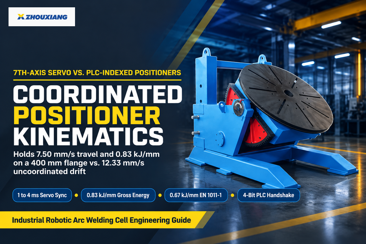
A coordinated external-axis positioner runs inside the robot controller’s kinematic solver to hold 7.50 mm/s (0.45 m/min) surface speed on a rotating 400 mm flange. That speed holds 0.83 kJ/mm gross arc energy (0.67 kJ/mm EN 1011-1 heat input), whereas uncompensated rotation hits 12.33 mm/s and drops arc energy to 0.51 kJ/mm (0.40 kJ/mm net).
- Driven by matching OEM servo amplifiers inside the robot controller cabinet
- Kinematic solver holds constant relative torch-to-surface speed during rotation
- Keeps molten weld pool in flat 1G downhand posture on pipes and vessels
- Requires paid multi-group motion software and calibrated leader-follower frames
- Driven by an independent AC vector drive via discrete PLC I/O
- Rotates only while the welding torch sits at a safe home interlock
- Exchanges 4 discrete handshake bits: Home Clear, Index, In-Position, Brake Locked
- Saves OEM servo licensing cost on flat multi-sided bracket fixtures
Buyers often purchase a standalone motorized turntable expecting any six-axis robot arm to weld continuously while the platter spins. Two separate controllers linked by a relay can’t synchronize 3D surface velocity across changing radii. Example: Assumed inputs are a 400 mm outer-diameter pipe flange rotating at 0.35 rpm under 240 A and 26 V GMAW (0.8 thermal factor per EN 1011-1). Part surface speed equals π × 400 mm × 0.35 rpm ÷ 60 = 7.33 mm/s (0.44 m/min). Under coordinated 7th-axis kinematics, the solver subtracts that 7.33 mm/s vector so net travel stays at 7.50 mm/s. Gross arc energy holds at 26 V × 240 A ÷ (1,000 × 7.50 mm/s) = 0.83 kJ/mm, giving 0.67 kJ/mm net EN 1011-1 heat input. Moving an uncoordinated torch counter to rotation at a 5.00 mm/s torch travel setting raises combined surface speed to 12.33 mm/s and cuts gross energy to 0.51 kJ/mm (0.40 kJ/mm net).
Return-current isolation is equally important on rotary and tilting welding positioners. Modern inverter power supplies run sensitive voltage feedback loops that fault when rotary ground resistance spikes. Integrators fit spring-loaded brass or graphite rotary sliprings alongside dielectric insulation between the servo motor, worm gearbox, and platter so stray current never pits bearings. On 6 to 15 m structural girders, headstock and tailstock welding positioners for long beams synchronize dual-end rotation to stop torsional twist.
When Should You Choose a Coordinated External Axis Over a PLC-Indexed Positioner?
A continuous servo axis can be used to weld a joint when a circumferential pipe joint or a vessel with a continuous fillet must rotate to maintain a flat 1G weld pool. Pick a PLC-indexed positioner when straight seams are welded stationary after a 90-degree or 180-degree index.
Flat structural brackets, trailer frames, and rectangular subassemblies rarely require paid OEM auxiliary servo drives and multi-group kinematics. A pneumatic shot-pin lock can be used to create repeatable, indexed positions and an In-Position limit switch can provide feedback to a PLC, which can control a weld positioning system.
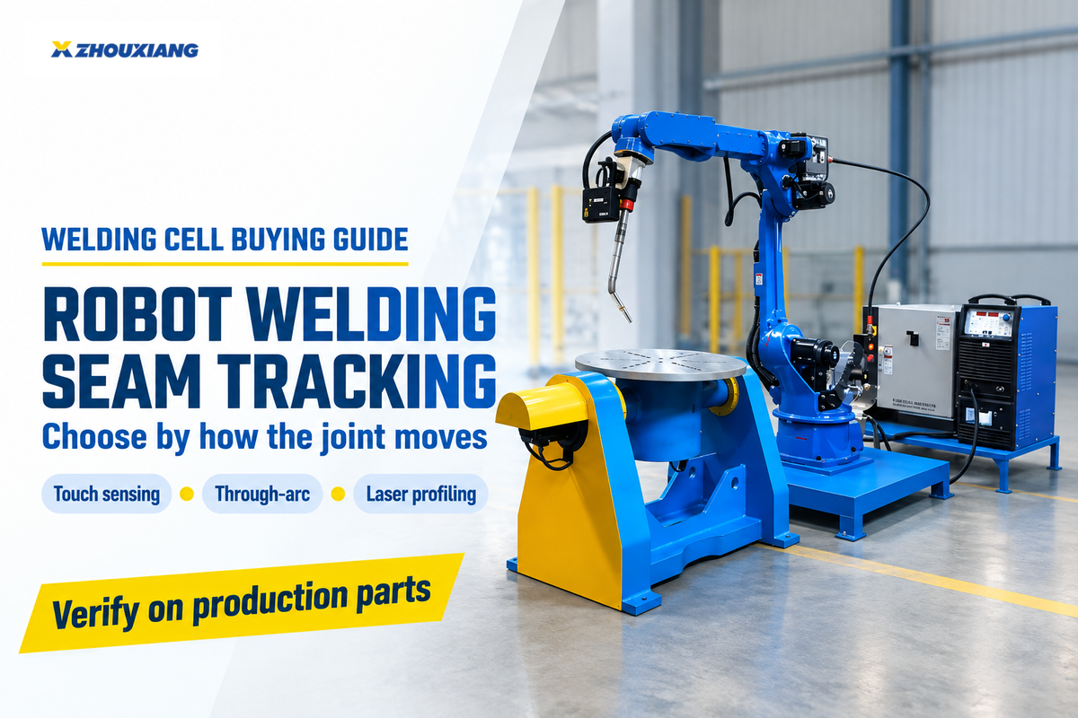
Seam-Tracking and Adaptive Control Loops: Touch Sensing, Through-Arc, and Laser Vision
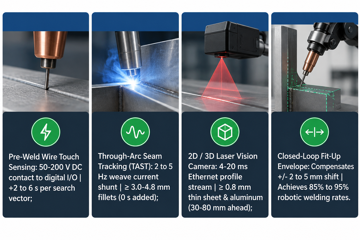
Industrial arc welding robots can correct joint shifts using three feedback loops. The first is a DC touch sensor that searches for a seam from 50 to 200 V and takes 2 to 6 seconds per search. Real-time Through-Arc Seam Tracking guides fillets 3 to 4.8 mm and thicker, while 3D laser cameras track thin sheet and aluminum.
“Before welding, vision systems enable seam finding and joint localization, eliminating time consuming manual programming. During welding, real-time seam tracking enables robots to compensate for joint variations and maintain optimal wire position. After welding, the same sensors inspect the finished weld bead, measuring size, shape, location, and defects.”
Each sensing method enters the controller through a different hardware channel. Wire or nozzle touch sensing uses a low-current DC search voltage from the welder or touch module. The arm moves until the clipped wire touches steel and stores a 3D start offset. Through-Arc Seam Tracking (TAST) works live during weaving at 2 to 5 Hz. The controller measures current on the left and right groove walls. Centerline position is adjusted to even out stick out. A closed loop architecture, such as in USPTO Patent US11623294B2, uses absolute torch-tip position sensors and relative joint position sensors to adjust the trajectory of the robot.
Matching sensor physics to joint geometry prevents tracking drop-outs in laser vision and through-arc seam tracking for welding robots. Mill scale and unclipped silica wire balls prevent DC touch contact, which is restored only if an automatic wire cutter trims the tip every cycle. Since TAST measures sidewall current changes, it loses lock on sheets less than 3 mm, tight butt joints, and aluminum. Those joints are addressed using 3D machine vision lasers, which are hardened and mounted 30-80 mm ahead of the arc. Properly designed vision-guided cells achieve 85% to 95% robotic welding rates, provided crews run routine TCP pointer checks to catch gradual neck or tip drift.
Can a Robot Welding Control System Compensate for Part Fit-Up Variation?
Yes. Touch sensing paired with TAST or 3D laser vision compensates for +/- 2 to 5 mm of joint position shift and moderate root-gap growth by shifting the path and adapting weave width. Sensors can’t fix loose clamping and excessive flame-cut gaps.
Technical guidance from The Welding Institute (TWI) states that automated cells require repeatable edge preparation and rigid clamping fixtures. If gusset gaps exceed the qualified weld root opening, adaptive wire feed can’t prevent burn-through without upstream fit-up control.
| Sensing Method | Controller Feedback Path | Minimum Wall / Joint Geometry | Cycle-Time Impact | Primary Shop Limitation |
|---|---|---|---|---|
| Pre-Weld Wire / Nozzle Touch Sensing | 50–200 V DC contact input to robot digital I/O | Lap, T-fillet, or groove with clean steel walls | +2 to 6 s per search vector before arc start | Blocked by heavy mill scale or unclipped wire ball; zero mid-weld tracking |
| Through-Arc Seam Tracking (TAST) | Real-time arc current shunt or fieldbus cyclic word | ≥ 3.0–4.8 mm steel fillets and V-grooves with weave | 0 s added pre-weld; tracks live during weaving | Loses lock on sheets thinner than 3 mm, square butt joints, or stringer beads |
| 2D / 3D Laser Vision Triangulation | High-speed Ethernet profile stream (4–20 ms offset) | Thin sheet (≥ 0.8 mm), butt, lap, fillet & aluminum | 0 s pre-weld hold with look-ahead tracking | Camera housing limits tight corner access; needs air-knife lens care |
Programming Interfaces and Weld Traceability: Teach Pendant, Lead-Through, and Offline CAD
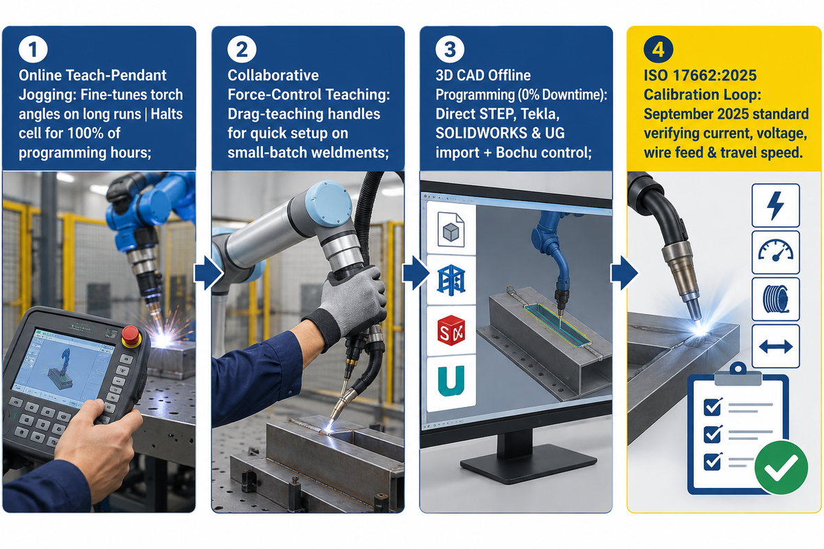
CAD-to-path offline robot programming builds collision-free weld trajectories on an office PC with 0% production cell downtime, whereas online teach-pendant jogging halts arc output for 100% of programming hours. At the station level, ISO 17662:2025 governs workshop calibration, verification, and validation of welding process-control equipment.
High-mix structural shops typically delay automating repetitive welding tasks due to the time required to jog 50 gusset seams by pendant. As reported in The Fabricator’s offline programming engineering guide, more than half of programmed points in welding are non-welding air moves around clamps. Offline welding software simulates a 3D kinematic copy of the arm and positioner, generating collision-free paths, while the shop floor runs production applications.
Three programming interfaces cover the modern needs of fabrication: the standard pendants fine-tune torch angles on long runs; and collaborative welding cobots add force controlled handles for quick drag teaching on small batches. For heavy steel, 3D CAD models are imported directly from STEP, Tekla, SOLIDWORKS, and UG, and cantilever stations integrate a Bochu intelligent control system for path generation.
For weld quality control, ISO 17662:2025 (replacing the withdrawn 2016 edition in September 2025) sets calibration and verification intervals for meters controlling current, voltage, wire feed, and travel speed. Calibrating controller displays and shunts to ISO 17662:2025 keeps delivered heat input repeatable across production shifts.
2026 Robotic Welding Cell Cost, Lead Time, and Controller Option Surcharges
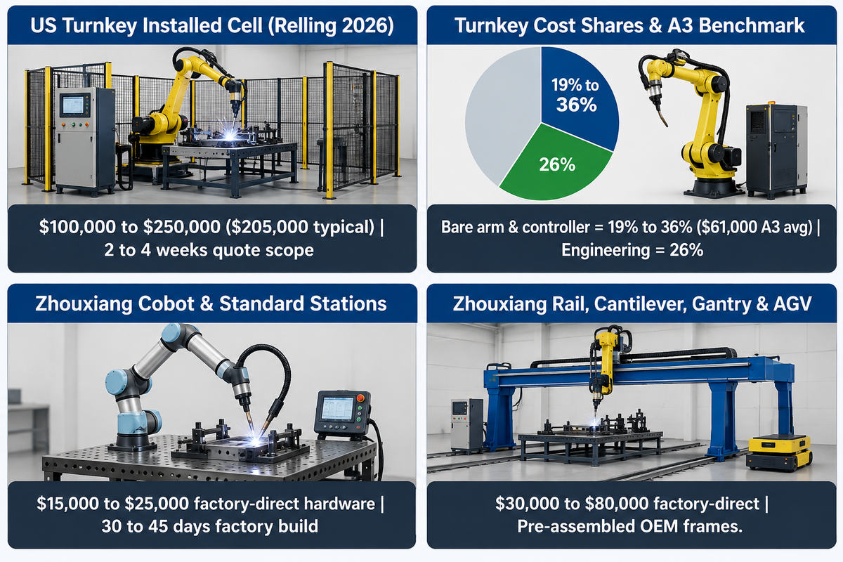
Software options, calibration scope, and integration labor drive 2026 cell budgets: US integrator stacks price turnkey installed single-robot welding cells at $100,000 to $250,000 ($205,000 typical). Factory-direct workstations from Wuxi Zhouxiang run $15,000 to $25,000 for cobot or compact stations and $30,000 to $80,000 for rail, cantilever, gantry, or AGV models (30 to 45 days build).
Why are turnkey quotes for systems using manipulators two to five times more than the cost of the bare manipulator? In 2026 US planning stacks from Relling Systems, the robot arm and controller represent only 19% to 36% of the installed cell. For reference, A3’s 2025 North American order data averages $61,000 per robot. Engineering, wiring, programming, and site commissioning account for 26% of a typical $205,000 welding cell (22% to 33% across cell types), while tooling, vision, positioners, and safety controls make up the rest. Standardized factory-direct welding solutions ship pre-assembled frames from the OEM plant, leaving local utility hookups to your shop crew.
Teams comparing robotic welding against manual welding throughput must also check what “positioner interface included” actually buys. For many controller quotes, this represents a cabinet connector or a software driver, as opposed to a worm-gear turntable and safety curtains. Adding a physical servo head stock, 3D laser camera and paid weld process software represents a significantly larger scope compared to a bare robotic arc welding arm. Accurately estimating payback for welding productivity depends on pricing real option deals for robotic welding.
How Much Does a Complete Robotic Welding Cell With Positioner Interface Cost?
Weighing the advantages of robotic welding against real option prices keeps welding productivity payback forecasts accurate. A complete North American turnkey single-robot welding cell with guarding, tooling, and positioner integration budgets $100,000 to $250,000 installed in 2026 (firm integrator quotes take 2 to 4 weeks to scope). Factory-direct modular workstations from Wuxi Zhouxiang budget $15,000 to $80,000 per piece with a 30 to 45 day factory production window.
A custom robotic welding operator positioner interface includes only the internal cabinet plug or the software driver. Customers still need to purchase a rotary table, an auxiliary servo amplifier, and light curtains for the load bay.
OEM Controller Ecosystems and Specifying Workstations for Structural Fabrication
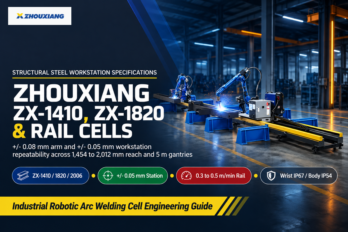
Buyers source robotic welding automation from three supplier tiers: global robotics OEMs (FANUC, Yaskawa, ABB, KUKA), welding-process OEMs (Lincoln Electric, Fronius, Miller), and structural workstation builders like Wuxi Zhouxiang. The repeatability of Zhouxiang’s ZX-1410, ZX-1820 and ZX-2006 robotic arms is +/- 0.08 mm arm repeatability and +/- 0.05 mm workstation repeatability.
Global factory installations keep expanding across the welding industry and wider manufacturing applications. Per the International Federation of Robotics (IFR) World Robotics 2025 report, plants installed 542,000 industrial robots globally in 2024 across all sectors, lifting active stock 9% to 4,664,000 units (including 34,200 new US units). For common robotic welding uses in industrial welding, global robot OEMs lead high-speed automotive lines. Welding-process OEMs focus on advanced robotic welding packages for thin alloy mig welding and aerospace arc welding applications.
Structural steel and heavy machinery plants face a larger envelope problem. Six-meter to fifteen-meter girders exceed a standard 1.4 to 2.0 m robot reach unless the robot welder travels on a ground rail, cantilever, or overhead gantry. Founded in 1991 with over 400 staff and ISO9001:2008 plus CE certification, Wuxi Zhouxiang builds industrial 6-axis and collaborative welding robot workstations for heavy plate and beam fabrication. Its 6-axis lineup spans the ZX-1410 (10 kg load, 1,454 mm reach, 170 kg), ZX-1820 (20 kg load, 1,730 mm reach, 285 kg), and ZX-2006 (6 kg load, 2,012 mm reach, 291 kg). Every arm carries Wrist IP67 and Body IP54 protection, pairing with 50 kVA, 2,500 kg AGV mobile stations. For straight heavy girders and high-deposition submerged arc welding uses, dedicated H-beam assembly and submerged-arc welding lines beat articulated cells and outpace multi-axis robotic welding solutions.
| Model / Cell Configuration | Payload / Reach / Span | Repeatability & Enclosure | Control & Sensing Highlights | Published Price / Build Scope |
|---|---|---|---|---|
| Zhouxiang ZX-1410 6-Axis Arm | 10 kg load / 1,454 mm reach (170 kg) | ± 0.08 mm; Wrist IP67 / Body IP54 | Compact 6-axis manipulator for standard weld cells | $20,000–$25,000 station (30–45 days) |
| Zhouxiang ZX-1820 6-Axis Arm | 20 kg load / 1,730 mm reach (285 kg) | ± 0.08 mm; Wrist IP67 / Body IP54 | Heavy-torch capacity for tandem/water-cooled GMAW | Factory-direct workstation integration |
| Zhouxiang ZX-2006 Extended Arm | 6 kg load / 2,012 mm reach (291 kg) | ± 0.08 mm; Wrist IP67 / Body IP54 | Extended 2 m envelope for wide structural frames | Factory-direct workstation integration |
| Zhouxiang Collaborative Cobot Station | Compact table / mobile cart footprint | ± 0.05 mm workstation repeatability | Force-control drag teaching + AI & laser tracking | $15,000–$20,000 factory-direct hardware |
| Zhouxiang Standard Welding Station | Single-cell fixed base configuration | ± 0.05 mm workstation repeatability | 6-axis robot + welding equipment + fixture base | $20,000–$25,000 factory-direct hardware |
| Zhouxiang AGV Mobile Workstation | 2,500 kg unit / up to 2.2 km/h travel | ± 0.05 mm; 50 kVA power rating | Autonomous floor navigation to oversized weldments | $30,000–$40,000 factory-direct hardware |
| Zhouxiang Ground-Rail Workstation | Linear rail travel 0.3–0.5 m/min | ± 0.05 mm; 4.5 kVA rail drive | STEP, Tekla, SOLIDWORKS & UG 3D CAD import | $30,000–$80,000 factory-direct hardware |
| Zhouxiang Cantilever / Gantry Station | Gantry spans up to 5 m for box/H-beams | ± 0.05 mm workstation repeatability | Bochu control, 3D point-cloud, ultrasonic probe & torch cleaner | $40,000–$80,000 (cantilever) / $70,000–$80,000 (gantry) |
| US / EU Turnkey Integrator Weld Cell | Single-arm cell + custom fixture & fence | ISO 10218-2:2025 / R15.06-2025 sign-off | FANUC / ABB / Yaskawa + EtherNet/IP or PROFINET PLC | $100,000–$250,000 installed ($205,000 typical, Relling) |
Prior to releasing a purchase order, complete the six-point interface matrix below and attach it to your Request for Quotation. That step puts one engineering team in charge of every electrical and software handshake prior to factory acceptance testing:
The 6-Point Cell Interface Pinout Matrix — Copy Into Your Robotic Welding RFQ:
| Parameter | Recommended range | Why it matters | How to verify |
|---|---|---|---|
| 1. Power-Source Protocol Card | 4–8 ms EtherNet/IP, PROFINET, EtherCAT, or 24 V + 0–10 V | Prevents mismatched RJ45 protocols between arm and welder | Match scanner/adapter EDS files & Job recall table before FAT |
| 2. Functional Safety Circuit | Dual-channel Cat. 3 PL d; ≤ 250 mm/s manual teach cap | Meets ISO 10218-2:2025, ANSI/A3 R15.06-2025 & plant EHS audit | Single-fault injection test on gate interlock, E-stop & STO |
| 3. Positioner Drive & Return | 1–4 ms servo kinematic sync or 4-bit PLC index + slipring | Holds constant kJ/mm heat input & stops stray bearing current | Continuous pipe rotation test + megohm check across servo mount |
| 4. Seam-Sensor Feedback Loop | 50–200 V touch + TAST (≥ 3 mm) or 4–20 ms 3D laser | Matches sensor physics to plate thickness and joint gap | Shift test piece ± 3 mm on FAT fixture and inspect fillet leg |
| 5. CAD / OLP & Calibration | STEP / Tekla / SOLIDWORKS import + ISO 17662:2025 log | Eliminates shop-floor pendant downtime on high-mix steel | Import sample customer STEP assembly & verify V/A meter accuracy |
| 6. Enclosure, Reamer & Ground | Wrist IP67 / Body IP54; ≤ 100 V OCV; star ground | Blocks spatter ingress, HF-GTAW EMI & OSHA 1910.254 faults | Inspect auto wire-cutter/reamer cycle & dedicated earth bond |
Specify every robot welding control system across four layers. Match a 4 to 8 ms fieldbus or analog welder card, dual-channel PL d safety stops (≤ 250 mm/s teach cap), servo or indexed positioners, and thickness-matched seam sensors.
Configure a Structural Steel or Heavy-Plate Robotic Welding Workstation
Is your factory thinking about gantry, ground rail or collaborative workstations for heavy sub-assemblies? Send your STEP, Tekla, SOLIDWORKS, or UG part drawings and power-source interface requirements to Wuxi Zhouxiang’s engineers.
Explore Zhouxiang Welding Robot Workstations & Request Free Layout Design →
Frequently Asked Questions About Robot Welding Control Systems
What is the difference between a welding robot controller and a cell PLC?
The welding robot motion controller implements inverse kinematics for six axes, as well as torch velocity and weave patterns every 1 to 8 ms. In the meanwhile, a cell PLC sequences 12 to 32 discrete I/O channels per station. This station PLC controls pneumatic clamps, part-present switches, shuttle transfers, nozzle reamers, and HMI without calculating continuous arm trajectories.
Do all robotic welding power sources require an Ethernet fieldbus card?
No. Constant-voltage gas metal arc welding, with the saved wire-feed speed and the voltage settings, runs cleanly with the hardwired discrete start/status pins and the two 0 to 10 V analog outputs. Industrial Ethernet fieldbuses like EtherNet/IP, PROFINET or EtherCAT become necessary for pulsed synergic trim, Through-Arc Seam Tracking and weld data logging.
What causes an arc-start timeout error in a robot welding control system?
An arc-start timeout occurs when the robot controller sends the Weld start signal at the ignition point, and, within 0.5 to 1.5 seconds, there’s no current feedback to confirm the establishment of an arc. Common causes in a shop include heavy mill scale, spatter fouled work ground clamps, wire-liner birdnesting, unclipped silica wire balls, or an empty shielding gas cylinder.
Why do high-frequency TIG starts interfere with robotic welding controllers?
The radio-frequency noise generated by high frequency GTAW pulses can induce interference into unshielded analog circuits and ground loops. The use of shielded digital fieldbuses, star building grounds and calibrated spark gaps can prevent controller resets.
How do collaborative welding robot controllers differ from fenced industrial robot controllers?
Collaborative robots use force-limiting torque controllers and hand-guided handles to teach the robot quickly in cobot welding, whereas fenced industrial controllers drive higher-speed multi-group servos. Industrial cabinets synchronize multi-ton positioners or 5 m gantry tracks across multi-shift heavy welding applications. Under ISO 10218-2:2025, both controller types still require arc-glare shielding, fume extraction, and hot-wire safeguarding.
Can you retrofit a modern welding power source onto an older robot controller?
Yes. Matching DeviceNet, EtherNet/IP or PROFINET cards – or a universal discrete and analog robot interface box – connect modern power sources to older robot controllers.
Does ISO 17662 certify that a robot welding control system produces code-compliant welds?
No. ISO 17662:2025 sets workshop accuracy checks for instruments controlling welding current, arc voltage, wire-feed speed, and travel speed across shifts. Code acceptance of finished structural steel or pressure welds still requires a qualified Welding Procedure Specification, sound joint fit-up, and post-weld visual or non-destructive examination under the governing structural welding code.
References & Sources
- ANSI/A3 R15.06-2025 (Parts 1, 2, and 3) Industrial Robots and Robot Systems Safety Requirements (Harmonized with ISO 10218-1:2025 & ISO 10218-2:2025) American National Standards Institute (ANSI)
- OSHA Technical Manual (OTM) Section IV: Chapter 4, Industrial Robot Systems and Industrial Robot System Safety U.S. Department of Labor, Occupational Safety and Health Administration (OSHA)
- 29 CFR § 1910.254 Arc Welding and Cutting U.S. Department of Labor, Occupational Safety and Health Administration (OSHA)
- Playing It Safe With Robotic Welding: Workcell Risk Assessment, Interlocks, and Safeguarding The Fabricator / The Welder (Fabricators & Manufacturers Association)
- An Innovative Approach to Welding Robot Operator Reliability Analysis Using Extended TESEO and HEART Methods (PMCID: PMC12595067) U.S. National Institutes of Health / National Library of Medicine
- The Next Evolution of Welding Automation and Inspection (Jeff Noruk) American Welding Society (AWS) Inspection Trends
- United States Patent US11623294B2: Methods and Systems Using a Smart Torch With Positional Tracking in Robotic Welding United States Patent and Trademark Office (USPTO / Google Patents)
- ISO 17662 Welding, Calibration, Verification and Validation of Equipment Used for Welding (Lifecycle Update to ISO 17662:2025) International Organization for Standardization (ISO)
- Offline Programming of Welding Robots: Simulation, Calibration, and Cycle-Time Reduction The Fabricator (Fabricators & Manufacturers Association)
- World Robotics 2025 Industrial Robots Report: Global Robot Demand in Factories International Federation of Robotics (IFR)
About This Control Architecture Analysis
This guide compiles electrical interface, functional safety, kinematic positioning, seam-tracking, and calibration rules across ISO 10218-1/2:2025, ANSI/A3 R15.06-2025, OSHA 29 CFR § 1910.254, OSHA Technical Manual Section IV Chapter 4, and ISO 17662:2025. It also pairs 2026 North American integrator cost stacks with OEM robot-interface data. Wuxi Zhouxiang Complete Set of Welding Equipment Co., Ltd. manufactures 6-axis welding robots (ZX-1410, ZX-1820, ZX-2006), ground-rail, cantilever, gantry, AGV, and cobot workstations, welding positioners, and H-beam welding lines. Specific fieldbus option cards and plant safety PLC interfaces are configured per project order. Reviewed by the Wuxi Zhouxiang Complete Set of Welding Equipment Co., Ltd. technical team.