Hardfacing welding rod types cover five principal AWS A5.13 alloy families rated from 18 HRC to over 70 HRC. Selecting the wrong electrode in industrial welding applications can wear out a part faster than if it is left bare. Using a brittle 60 HRC chromium carbide rod on a crusher hammer results in the overlay spalling off. Using a soft manganese pass in a fine sand chute can also fail, since low-stress sliding never causes work-hardening.
This engineering guide correlates classifications from AWS A5.13 hard surfacing with sliding abrasion, impact, metal-to-metal friction, and thermal corrosion. You will learn how base-metal dilution alters first-pass chemistry across diverse hardfacing applications. We also explain when buffer layers are mandatory and how manual stick overlays differ from automated beam fabrication.
How Are Hardfacing Welding Rod Types Classified by AWS A5.13 and Wear Mechanism?
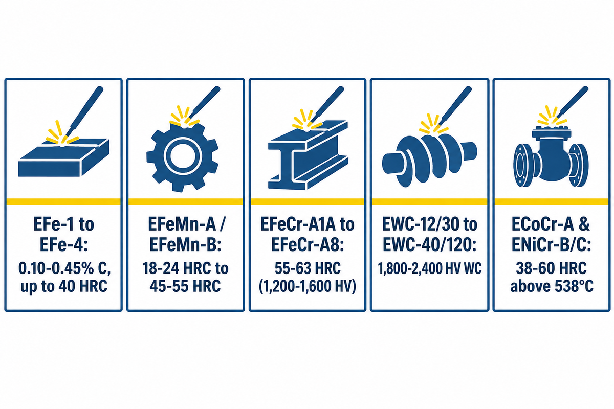
Hardfacing welding rod types under AWS A5.13/A5.13M:2024 divide into five metallurgical families spanning 18 HRC to 70 HRC equivalent. According to AWS A5.13 surfacing electrode specifications, covered electrodes for shielded metal arc welding fall into five chemical groups. These groups cover iron-base, cobalt-base, nickel-base, copper-base, and tubular tungsten carbide grades. Each class balances impact toughness, wear resistance, and carbide volume for specific service conditions.
Before comparing surfacing alloys, engineers who need conventional joint fillers should review our structural welding rod selection guide. Structural electrodes are rated by tensile strength in thousands of pounds per square inch (psi). Surfacing electrodes, on the other hand, are defined by their undiluted chemistry in weld metal, in accordance with AWS A5.13. That undiluted chemistry is typically measured on the second or third weld layer.
According to The Fabricator’s SMAW hardfacing electrode guide, the rate of deposition of surfacing by manual stick process is in the range of 1 to 7 lb/hr (0.45 to 3.2 kg/hr). The stick arc is reported to give 15% to 30% base-metal dilution on the first pass. Because the welding arc mixes parent metal into the molten pool, first-pass hardness drops below the rated values. Medium hardness martensitic alloys and high-chromium alloys require fine tuning of amperage and layer counts to achieve rated wear resistance.
| AWS A5.13 Family & Typical Class | Key Undiluted Alloy Content | Typical Deposit Hardness | Machinability & Relief Checks | Max Recommended Layers | Primary Wear Mechanism |
|---|---|---|---|---|---|
| Low-Alloy Buildup & Martensitic Steel (EFe-1 to EFe-4) | 0.10–0.45% C, 1–4% Cr, Mn, Mo | 25–55 HRC | Machinable up to ~40 HRC; check-free deposit | 3 layers to unlimited (EFe-1) | Metal-to-metal rolling, sliding, and moderate impact restoration |
| Austenitic Manganese Steel (EFeMn-A, EFeMn-B, EFeMnCr) | 0.5–0.9% C, 11–14% Mn, 3–5% Ni or Cr | 18–24 HRC as-welded; 45–55 HRC work-hardened | Non-machinable (grind only); ductile check-free matrix | Unlimited (if interpass stays below 260°C / 500°F) | Severe rock-on-metal pounding and extreme gouging impact |
| High-Chromium Carbide Iron (EFeCr-A1A to EFeCr-A8) | 3.0–5.0% C, 20–35% Cr, optional Mo/Nb/V | 55–63 HRC bulk (carbides 1,200–1,600 HV) | Grind only; cross-bead relief checks every 10–19 mm | 1 to 2 layers max (max 3 layers in special cases) | Severe low- or high-stress sliding mineral abrasion |
| Tubular Tungsten Carbide (EWC-12/30, EWC-20/30, EWC-40/120) | 40–60 wt% WC/W2C granules in mild steel tube | Matrix 45–55 HRC; WC granules 1,800–2,400 HV | Non-machinable; fine surface relief checks | 1 to 2 layers max | Extreme earth, sandstone, and mineral cutting or drilling |
| Cobalt-Base & Nickel-Base Alloys (ECoCr-A / Stellite 6, ENiCr-B / ENiCr-C) | 25–32% Cr, 4–14% W or 2–4% B, balance Co or Ni | 38–45 HRC (ECoCr-A); 45–60 HRC (ENiCr-B/C) | Machinable with carbide tooling (ECoCr-A); requires preheat | 2 to 3 layers over stainless buffer | High-temperature wear above 538°C (1,000°F), cavitation, and acidic corrosion below pH 7 |
Recent metallurgical developments also target single-pass efficiency. For example, US Patent 9,475,154 B2 discusses a hardfacing electrode that deposits an iron-chromium-boron-carbon (Fe-Cr-B-C) matrix containing 2.5 to 4.5 wt% boron. Borocarbides are the primary phase that hardens the alloy. That chemistry forms dense primary borocarbides in a single pass, compensating for first-layer base metal dilution on field repairs.
Matching Wear Mechanisms to Deposit Metallurgy: Abrasion vs. Impact Trade-Offs
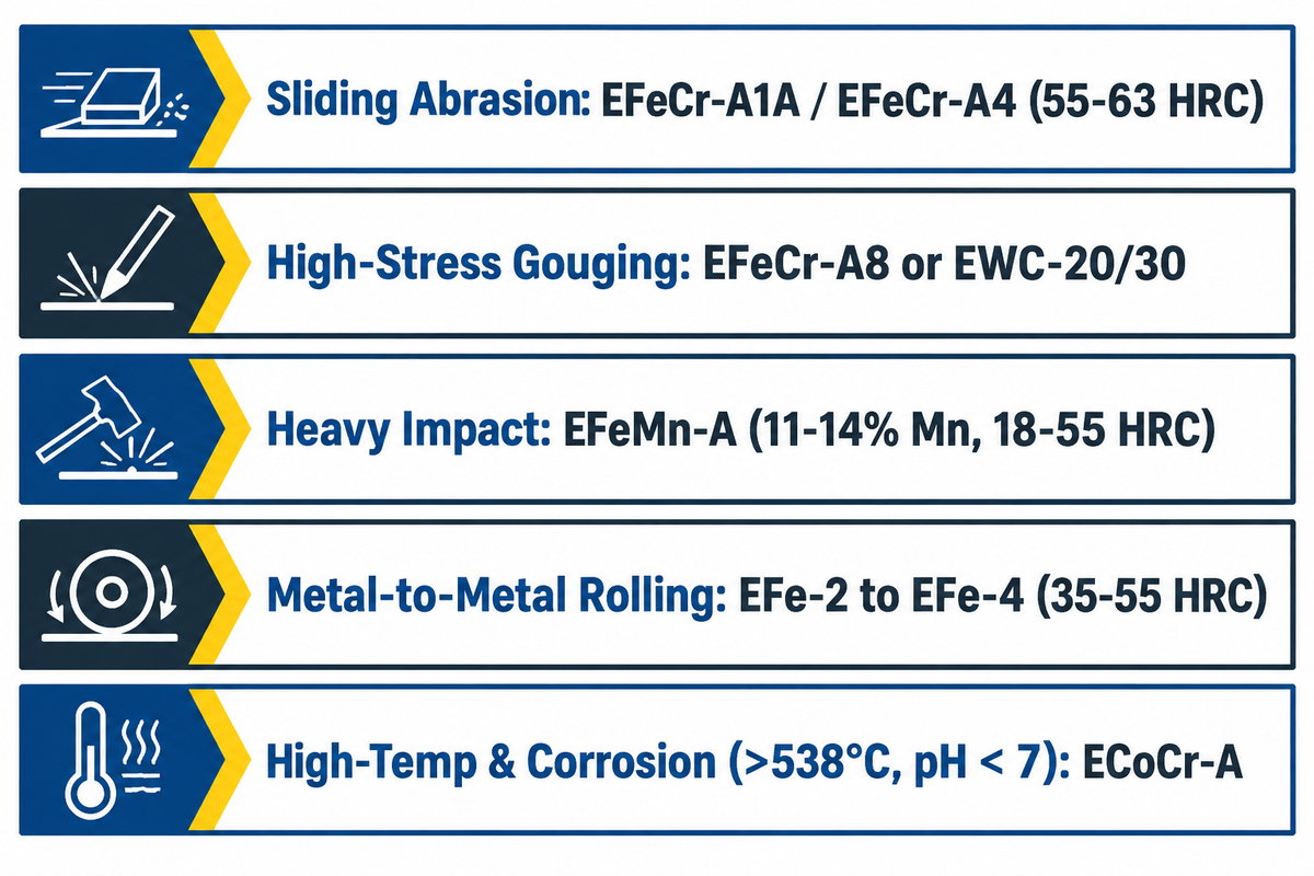
The first step in determining the alloy composition for a given application is to understand the dominant wear mode on a failed component. In services where hard facing occurs, abrasion resistance and impact toughness are inversely related to the volume of carbides. Adding primary tungsten and chromium carbides increases wear resistance against mineral scratching, whereas solid wire buildups favor impact ductility.
As explained in The Fabricator’s primer on hardfacing metal, two alloys with the same 58 HRC hardness can give very different service life. A 58 HRC martensitic tool-steel overlay contains almost no primary carbides, therefore quartz sand flows freely through the matrix. On the other hand, a 58 HRC high-chromium carbide deposit has hard M7C3 carbides that block mineral penetration.
| Wear Mode | Field Visual Signature on Worn Part | Recommended Microstructure | Preferred AWS A5.13 Class | Failure Risk if Misapplied |
|---|---|---|---|---|
| Low-Stress Sliding Abrasion | Smooth, polished grooves from fine sand, coal, cement, or grain flow | High volume fraction of hypereutectic M7C3 chromium carbides | EFeCr-A1A / EFeCr-A4 (25–35% Cr, 3.5–5.0% C) | Spalls rapidly if exposed to direct boulder impact or >2 layers |
| High-Stress Grinding & Gouging | Deep scratches, chipped edges, and embedded rock fragments | Complex carbides (Cr, Nb, Mo) or coarse WC granules in tough matrix | EFeCr-A8, Complex Carbide, or EWC-20/30 | Overheating WC puddle dissolves tungsten into brittle iron-tungsten |
| Heavy Impact & Pounding | Mushroomed lips, plastic deformation, and work-hardened cracks | Metastable austenite that transforms to martensite under shock | EFeMn-A or EFeMnCr (11–14% Mn) | Wears rapidly in pure sliding sand because surface stays at 20 HRC |
| Metal-to-Metal Rolling & Adhesion | Galling, spalled rollers, and plastically crushed shaft journals | Fine untempered or tempered lath martensite (check-free) | EFe-2, EFe-3, or EFe-4 (35–55 HRC) | Low resistance to sharp mineral silica abrasion |
| High-Temp & Corrosive Wear | Oxidation scaling above 538°C (1,000°F) or chemical pitting at pH < 7 | Cobalt-chromium-tungsten or nickel-chromium-boron solid solution + carbides | ECoCr-A (Stellite 6) or ENiCr-C | Cracks if applied without 315–482°C preheat and E309L buffer layer |
Operating temperatures and slurry chemistries set firm metallurgical boundaries. According to AWS Welding Digest’s best weld overlay practices, iron-base chromium carbide overlays lose hot hardness rapidly above 1,000°F. They also cannot replace cobalt- or nickel-base alloys in acidic slurries below pH 7. This is true for furnace grates and hot shear blades, as well as chemical mixer paddles.
What kinds of welding rods are best for hardfacing?
High-chromium carbide rods (AWS EFeCr-A1, 55 to 63 HRC) are best for sliding abrasion, while austenitic manganese rods (EFeMn-A, 18 to 55 HRC) are best for heavy rock impact. Martensitic steel electrodes (AWS EFe-2 to EFe-4, 40 to 55 HRC) perform best on metal-to-metal rollers and shafts.
For the highest wear protection for extreme mineral cutting, tubular tungsten carbide rods (EWC, 1,800 to 2,400 HV granules) are the best. For red-hot valves and dies operating above 538°C (1,000°F), cobalt-base ECoCr-A (Stellite 6) electrodes remain the industry standard.
Buildup and Buffer Electrodes vs. Hardfacing Cap Rods (And Why E7018 Alone Fails Abrasion)
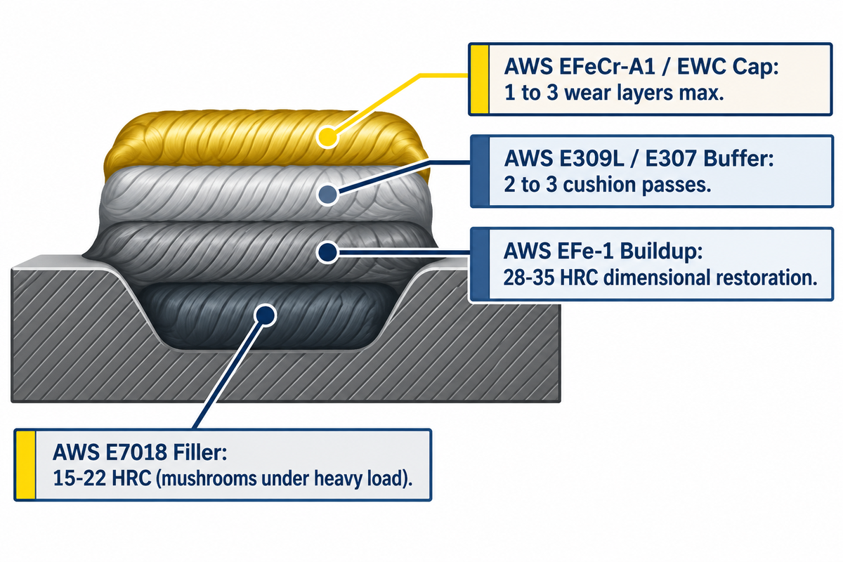
In the restoration of deeply worn parts, it is necessary to separate dimensional restoration from outer abrasion resistant cap layers. As documented in Hardface Technologies’ engineering FAQ, buildup alloys restore worn metal parts to near-original dimensions without a strict layer limit. Hardfacing cap alloys, however, have a strict layer limitation of one to three layers. Attempting to restore lost thickness on carbon and low alloy steels using a high-chromium cap rod will guarantee spalling.
Prior to the application of any buildup pass on a fatigued steel, the surface must be prepared. According to the AWS A5G Subcommittee guidelines, a minimum of 1/8-inch of material must be removed using either grinding or carbon-arc gouging. Direct application of high-chromium carbide cap rods over more than two degraded hardfacing layers, in the absence of stripping or buffering, will result in catastrophic spalling.
Laying cobalt-base ECoCr-A or high-shrinkage carbide overlays on crack-sensitive substrates requires an austenitic stainless steel buffer layer. Applying two to three buffer layers of AWS E309L or E307 creates a ductile cushion at the fusion interface. Readers comparing standard structural rods can check our breakdown of common stick welding electrode classifications.
| Foundation / Layer Type | Typical AWS Designation | As-Welded Hardness | Maximum Pass Limit | Primary Engineering Function |
|---|---|---|---|---|
| Structural Low-Hydrogen Filler | AWS A5.1 E7018 | 15–22 HRC (~190–210 HB) | Multi-pass structural joints | Joining mild steel; poor compressive support under heavy rolling loads |
| Dedicated Low-Alloy Buildup Rod | AWS A5.13 EFe-1 (e.g., Wearshield BU) | 28–35 HRC | Unlimited passes | Dimensional restoration; resists subsurface plastic mushrooming under hard caps |
| Austenitic Stainless Buffer Layer | AWS A5.4 E309L / E307 | 18–22 HRC (work-hardens to ~35–40 HRC) | 2 to 3 cushion passes | Crack-stopping stress-relief cushion between parent metal and brittle carbide caps |
| Hardfacing Cap Overlay | AWS A5.13 EFeCr-A1 / EWC | 55–65+ HRC | 1 to 2 layers max | Sacrificial wear-resistant outer shell; never used for deep thickness build-up |
Can you use 7018 for hardfacing?
AWS E7018 cannot be a final hardfacing wear layer because its deposit measures 15 to 22 HRC. It wears away under mineral abrasion. Low-hydrogen E7018 can be a base buildup filler layer on mild steel parts under light sliding wear. With heavy compressive or impact loads, E7018 plastically deforms (“mushrooms”) and yields under the hard surface, which causes the outer brittle layer to crack and delaminate.
When rebuilding rollers, shafts, or bucket lips under high compressive stress, replace E7018 with a dedicated buildup electrode (AWS EFe-1, 28 to 35 HRC). Apply it after the dimensional buildup is completed.
Iron-Base Hardfacing Electrodes: Martensitic Steel, Austenitic Manganese, and Chromium Carbide
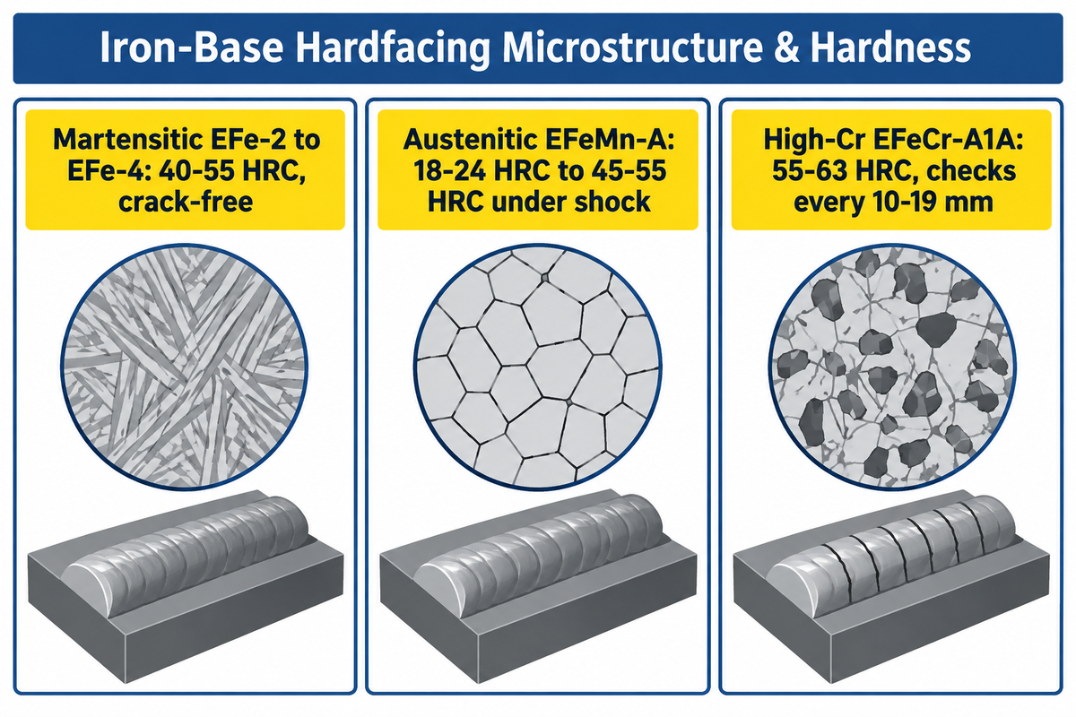
Iron-base hardfacing alloys account for the majority of maintenance stick welding because of their cost to performance ratio. Selecting between martensitic hardfacing alloys, austenitic manganese steel rods, and high-chromium carbide alloys depends on how each microstructure absorbs energy.
Members of the Martensitic steel electrode group (AWS EFe-2 through EFe-4) develop a lath or plate martensite structure on air cooling. These deposits harden to a range of 40 to 55 HRC (The Fabricator’s SMAW electrode specifications). Because they solidify without a cross-check, they tolerate a moderate amount of abrasion and impact up to two or three layers.
Austenitic manganese electrodes (AWS EFeMn-A and EFeMn-B) contain 11% to 14% manganese stabilized with nickel or molybdenum. According to The Fabricator’s SMAW electrode specifications, austenitic manganese deposits measure a soft 18-24 HRC as-welded and work-harden to 45-55 HRC under rock pounding. But if a welder applies austenitic alloys within a coal chute without impact, the metal stays soft and wears out quickly.
High-chromium carbide electrodes (AWS EFeCr-A1A through EFeCr-A8) pack high chromium and carbon into the weld metal to form dense hexagonal M7C3 carbides. According to AWS Welding Digest, controlled dilution creates a ductile transition zone in about 25% of the total thickness of the weld. That leaves the upper three-quarters of the weld a primary chromium carbide that effectively stops severe mineral sliding wear.
| Iron-Base Subgroup | Matrix & Carbide Structure | As-Welded vs. Service Hardness | Cross-Check Behavior | Ideal Industrial Application |
|---|---|---|---|---|
| Martensitic Air-Hardening Steel (EFe-2 to EFe-4) | Martensitic matrix with minimal retained austenite | 40–55 HRC immediately after cooling | Crack-free when preheat is maintained | Kiln trunnions, undercarriage rollers, shear blades, and shaft journals |
| Austenitic Manganese Steel (EFeMn-A / EFeMn-B) | Tough austenitic matrix; transforms under shock | 18–24 HRC as-welded → 45–55 HRC after impact | Ductile, zero cross-checks | Jaw crushers, gyratory cones, hammermill hammers, and railroad frogs |
| High-Chromium Carbide Iron (EFeCr-A1A to EFeCr-A8) | 30–50% primary M7C3 carbides (1,200–1,600 HV) in eutectic matrix | 55–63 HRC bulk macro-hardness | Desirable relief checks every 10–19 mm (3/8–3/4 in.) | Chute liners, sinter crusher bars, dredge pump casings, and auger flights |
Extreme-Service Alloys: Tungsten Carbide Tubular Rods, Cobalt-Base (Stellite), and Nickel-Base
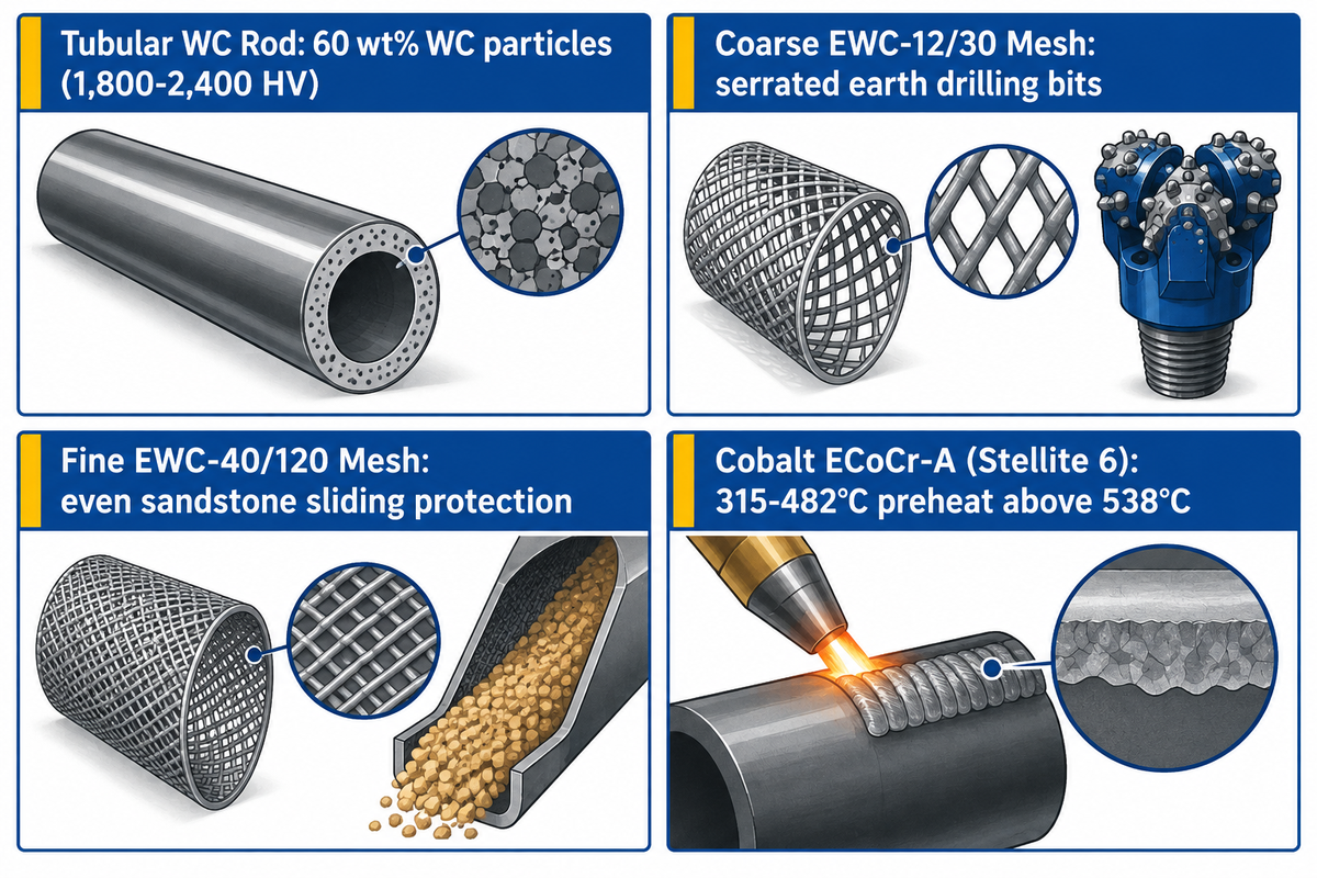
When abrasive minerals exceed 1,200 HV hardness or operating temperatures climb past 538°C (1,000°F), iron-base carbide hardfacing products reach their limits. In very severe conditions, such as abrasive wear, extreme-service tubular tungsten carbide, cobalt-base or nickel-base welding electrodes are often used to protect the components. Matching the welding process and amperage to these specialty rods prevents costly metallurgical damage.
Tubular tungsten carbide electrodes consist of a mild steel tube filled with approximately 60 wt% cast WC/W2C or macrocrystalline WC particles. This composite structure is documented in US Patent 4,923,511 A. Under AWS A5.13 Table 4, designations such as EWC-12/30, EWC-20/30, EWC-30/40, and EWC-40/120 specify the tungsten granule mesh size. Coarse 12/30 mesh particles create a serrated cutting edge on earth drilling bits. Fine 40/120 mesh granules distribute evenly against sandstone sliding wear.
Welders applying tungsten carbide rods must run the lowest possible amperage that maintains a smooth welding arc. Excessive current dissolves the 1,800 to 2,400 HV tungsten carbide granules into the iron puddle. Thermal dissolution of the granules creates an amorphous and brittle iron-tungsten matrix that fractures on contact. Stringer beads without wide oscillation keep the dense WC granules suspended.
Cobalt-base electrodes (such as AWS ECoCr-A, known as Kennametal Stellite 6) and nickel-base alloys (AWS ENiCr-B and ENiCr-C) dominate high-heat service. According to AWS Welding Digest, cobalt-base alloys require preheating between 600°F (315°C) and 900°F (482°C) over two to three buffer layers. They also require slow cooling with insulating blankets. Cobalt base alloys retain hot hardness in steam valves and hot extrusion dies. Precision valve seats often use tig welding rods of the same cobalt alloy.
Base Metal Compatibility: Carbon Steel, Hadfield Manganese, Wear Plate, and Cast Iron
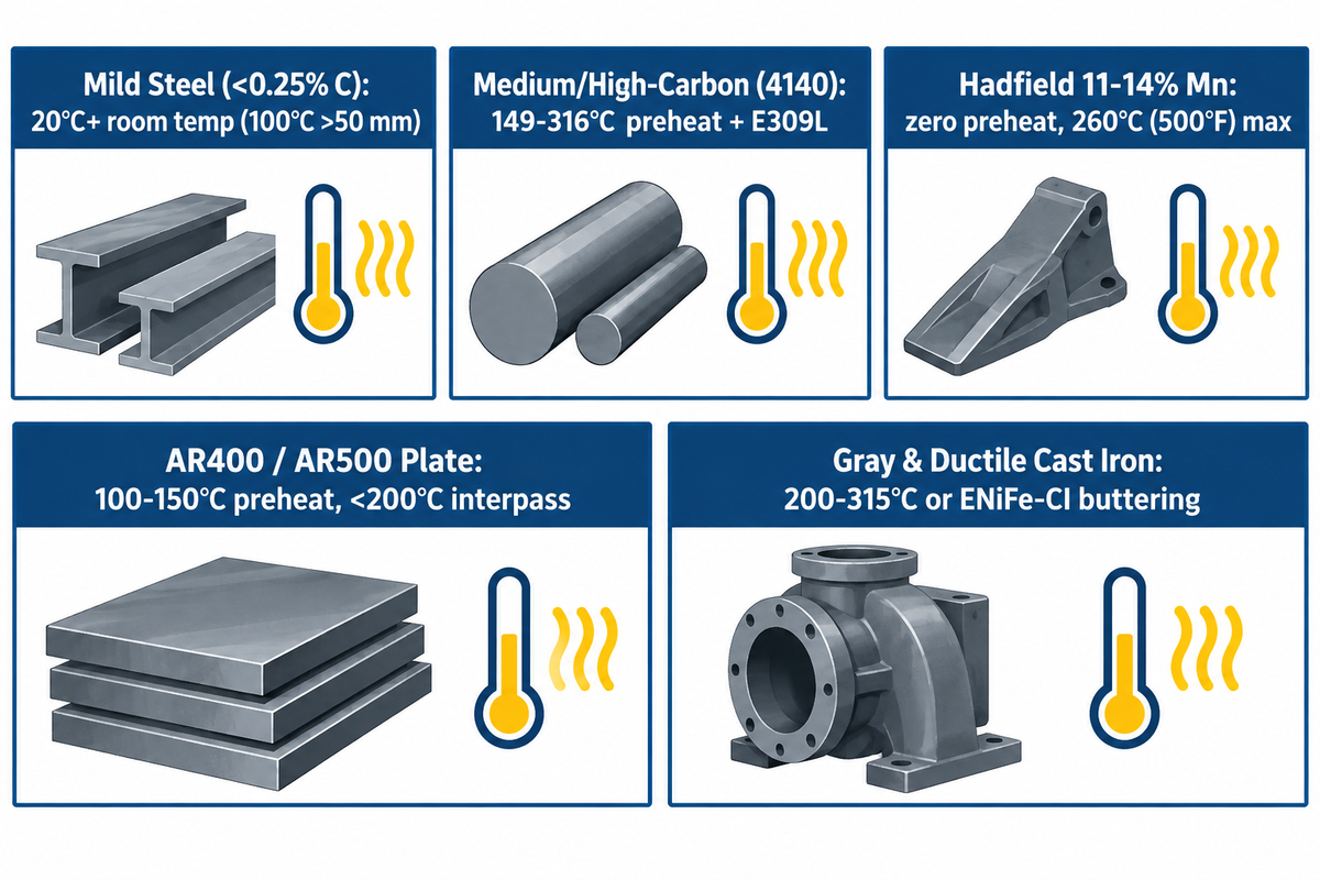
Base metal composition determines preheat or strict heat input restriction before applying hardfacing. Our five-engine baseline synthesis across 24 live queries revealing that generic tables omit the inverse preheat rule between medium-carbon steel (150–260°C preheat required) and Hadfield 12–14% manganese steel (zero preheat, <260°C / 500°F interpass ceiling) highlights this shop-floor hazard. Treating every steel casting like mild steel is one of the fastest ways to crack an expensive mining part.
According to Hardface Technologies’ preheat FAQ, alloy steels such as 4130 require preheating to about 400°F (200°C), while high-carbon steel rails require 600°F to 700°F (315°C to 370°C). Preheating slows the cooling rate in the heat-affected zone (HAZ), preventing brittle untempered martensite and hydrogen-induced underbead cracking.
Hadfield austenitic manganese steel (11% to 14% Mn) requires the exact opposite thermal protocol. Preheating Hadfield manganese steel or allowing interpass temperatures to exceed 500°F embrittles the casting with grain boundary carbides, as emphasized in AWS Welding Digest. As emphasized in AWS Welding Digest , if a manganese casting is below freezing in winter, warm it only to 80°F and keep interpass temperature strictly below 500°F.
| Base Material Type | Preheat Requirement | Maximum Interpass Ceiling | Required Buffer / First Pass | Critical Metallurgical Hazard |
|---|---|---|---|---|
| Low-Carbon Mild Steel (<0.25% C) | Room temp (20°C+); 100°C on thick plate >50 mm | 300°C (572°F) | None for 1–2 cap passes; EFe-1 for deep build-up | First-layer dilution (25–30%) reduces single-pass hardness |
| Medium/High-Carbon & Low-Alloy Steel (0.30–0.55% C, 4140) | 149°C to 316°C (300°F to 600°F) | 350°C (660°F) + slow blanket cool | Low-hydrogen E7018, EFe-1, or E309L buffer | HAZ martensitic transformation and hydrogen underbead spalling |
| Hadfield Austenitic Manganese Steel (11–14% Mn) | Zero preheat (warm chill to max 27°C / 80°F only) | Strict 260°C (500°F) max | EFeMn-A, EFeMnCr, or E307/E309L stainless | Time-temperature carbide precipitation causes parent metal tear-out |
| Quenched & Tempered Wear Plate (AR400, AR500, Hardox) | 100°C to 150°C (212°F to 300°F) on thick sections | 200°C (392°F) max | E309L or E7018 buffer under carbide caps | Overheating above 200°C tempers and softens the Q&T wear plate |
| Gray & Ductile Cast Iron (2.5–4.0% C) | 200°C to 315°C (400°F to 600°F) or cold skip-weld | Keep uniform; slow cool in lime/blanket | AWS A5.15 ENiFe-CI nickel-iron buttering pass | Carbon pickup forms brittle white iron along the fusion line |
What type of wire should you use to weld to hardfacing?
Use an austenitic stainless steel buffer electrode (AWS E309L or E307) or gasless FCAW E309LT0-3 cored welding wire after grinding off old hardfacing. Never weld a structural attachment or replacement wear lip directly to an existing chromium carbide or tungsten carbide overlay. The brittle carbide layer will fracture underneath the structural joint. Always carbon-arc gouge or grind the joint zone to sound parent metal before welding with E309L or AWS E7018 filler metal.
Dilution Math, Maximum Layer Limits, Relief Checking, and Bead Pattern Selection
Penetration and dilution govern whether a hardfacing welding rod achieves its catalog abrasion resistance in the field. It is estimated that during a shielded metal arc welding, 15% to 30% of the first layer of weld bead consists of melted base metal. Comparative wear testing in peer-reviewed Metals hardfacing overlay studies shows laboratory base coupons of 96 to 98 g increasing to 103 to 108 g after hardfacing deposition.
To see why two passes are required, consider an illustrative worked example assuming a two-pass SMAW dilution mass-balance model showing how 30% first-pass dilution into 0.18% C mild steel reduces an EFeCr-A1 deposit from 28.0% Cr / 4.5% C to 19.6% Cr / 3.18% C in Pass 1 (46–48 HRC) and restores 25.5% Cr / 4.11% C in Pass 2 (57–60 HRC), explaining why a 2-pass cap hits full abrasion resistance while a 3rd pass exceeds the spalling stress threshold. Using the mass-balance equation C_deposit = (D × C_base) + ((1 − D) × C_filler), Pass 1 solidifies near the eutectic boundary with reduced primary carbides. By Pass 2, hypereutectic M7C3 primary carbides return to full density.
The 2-Layer Relief-Check Threshold Rule
The 2-Layer Relief-Check Threshold Rule states that high-chromium carbide overlays (AWS EFeCr-A1 to EFeCr-A8) require 2 layers on carbon steel. Two passes help reduce base-metal dilution to less than 15% and restore primary M7C3 carbide density. These beads must develop transverse check-crack relief checks every 10 to 19 mm (3/8 to 3/4 in.). Crucially, the cap should never exceed 2 layers (6-8 mm total thickness) unless isolated by a ductile buffer layer.
Hardface Technologies has confirmed that in chromium carbide deposits, transverse relief checks every 3/8 to 3/4 in. are common and normal. If an overlay fails to check-crack, residual tensile stress builds along the fusion line until impact peels the overlay off.
Bead geometry controls wear life. Weave beads, according to The Fabricator, should not exceed three to four times the electrode core wire diameter. Because of the fluidity of hardfacing slag, cylindrical rollers, shafts, and buckets should be positioned in the 1G flat position. Shops use L-type rotary welding positioners for flat-position overlays to prevent weld pool sagging.
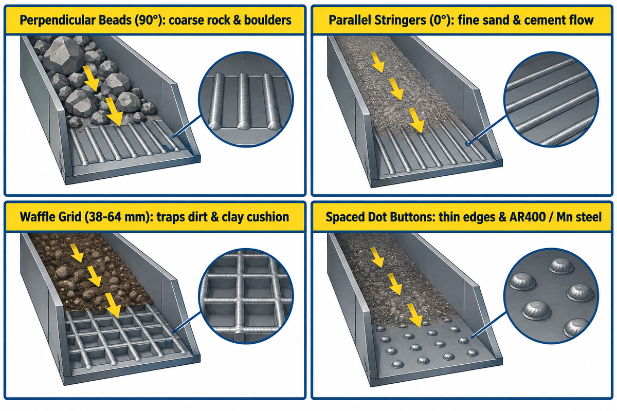
Orienting the weld bead relative to material flow turns the abrasive medium against itself, as shown in Hardface Technologies’ bead pattern guidelines:
- Perpendicular beads oriented at 90 degrees to flow work best for large boulders and coarse rock sliding down chutes. Large rocks ride across the bead crests without gouging the base material.
- Parallel stringer beads, oriented at 0 degrees to flow, work best for free-flowing particles of cement. Fine particles slide smoothly without eddy-current scouring between passes.
- Waffle or cross-hatch patterns work best for soil, clay or mixed rock and dirt, and should be spaced at 38 to 64 mm (1.5 to 2.5 in.). The grid compacts a stationary cushion of dirt, which wears against rock.
- For thin cutting edges, manganese castings, and heat-sensitive AR400 wear plates, dot patterns made of spaced weld buttons are best. Spaced dots avoid continuous heat buildup along thin edges.
Can hardness values be used to predict abrasion resistance?
No, bulk Rockwell hardness (HRC) alone cannot predict abrasion resistance across different alloy families. As noted in ASTM G65 dry-sand rubber-wheel testing and The Fabricator’s metallurgical comparisons, a 58 HRC chromium carbide deposit outlasted a 58 HRC martensitic steel deposit by three to five times in silica sand.
Macro-hardness only predicts wear life when comparing two overlays within the same metallurgical family. For example, a 52 HRC martensitic steel rod would outwear a 45 HRC martensitic steel rod under the same rolling friction.
Component Selection Matrix: From Excavator Buckets and Crusher Jaws to Heavy Structural Fabrication
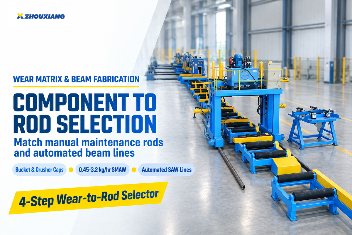
Mapping industrial equipment parts to the right filler combination avoids premature wear and heat affected cracking. Maintenance engineers can apply the 4-Step Wear-to-Rod Selector prior to issuing shop work orders.
The 4-Step Wear-to-Rod Selector Framework
- First, verify parent metal chemistry with a magnet test. Non-magnetic steel indicates 11–14% Hadfield manganese steel (strict 260°C / 500°F interpass ceiling), while magnetic steel indicates carbon or low-alloy steel.
- Second, strip fatigued metal and lay the foundation layer. Gouge off 3.2 mm (1/8 in.) of fatigued metal and lay EFe-1 passes for deep wear or 2 passes of E309L buffer under high shock caps.
- Third, match the cap alloy to the dominant wear mode. Choose EFeMn-A for heavy rock impact, EFe-3 martensitic for metal-to-metal rollers, EFeCr-A1 for mineral sliding abrasion, or EWC for extreme rock cutting.
- Fourth, ensure the orientation of layer caps and beads. Stop at 2 layers for chromium or tungsten carbide caps, and orient beads perpendicular for coarse rock, waffle for dirt, or parallel for fine sand.
| Industrial Component | Base Metal Substrate | Dominant Wear Mechanism | Recommended Buildup / Buffer | Recommended Hardfacing Cap Rod | Layer Limit & Bead Pattern |
|---|---|---|---|---|---|
| Excavator Bucket Teeth & Lips | Low-alloy cast steel or AR400 | High-stress rock gouging + moderate impact | EFe-1 buildup + E309L buffer on high-shock corners | EFeCr-A1A or Complex Carbide (58–62 HRC) | 2 layers max; waffle pattern in dirt, parallel in sand |
| Jaw & Cone Crusher Liners | 11–14% Hadfield manganese steel | Extreme rock pounding & compressive impact | EFeMn-A or E307 buffer (zero preheat, <260°C interpass) | EFeMnCr or single-layer EFeCr-A1 chunk/dot overlay | Stringer or dot pattern; water-cool skip welds |
| Mining & Cement Auger Flights | Mild steel or medium-carbon steel | Severe low-stress sliding silica abrasion | None required unless flight edge is worn thin | EFeCr-A1 or EWC-40/120 tubular tungsten carbide | 1–2 layers along outer flight edge and face |
| Bulldozer & Grader Cutting Blades | Medium-carbon / boron alloy steel | High-stress earth abrasion + shock | Preheat 150–200°C; E7018 or EFe-1 root repair | EFeCr-A4 or Martensitic-Carbide blend (52–58 HRC) | 2 layers max; 40–50 mm weave or herringbone |
| Dredge Cutterheads & Slurry Casings | Carbon or cast alloy steel | High-velocity wet sand erosion + impact | EFe-1 dimensional restoration | EFeCr-A1A (28–32% Cr) or EWC-20/30 on teeth | 2 layers; closely spaced stringers |
| Hot Shear Blades & Forging Dies | H13 / 4140 alloy tool steel | Thermal shock above 538°C + metal-to-metal shear | Preheat 315–450°C + 2 layers E309L stainless | ECoCr-A (Stellite 6) or ENiCr-B | 2–3 layers; slow cool in thermal blanket, machine to size |
| Steel Mill & H-Beam Conveyor Rollers | AISI 1045 / 4140 forged steel | Metal-to-metal rolling load + mill scale wear | Preheat 200–260°C + EFe-1 buildup | EFe-2 or EFe-3 martensitic steel (38–48 HRC) | 2–3 circumferential layers on rotary positioner |
| Structural Clamping & Straightening Rolls | Low-alloy structural steel | High compressive contact + sliding scale | EFe-1 machinable buildup | EFe-3 or EFe-4 martensitic tool-steel overlay | 2–3 layers; grind smooth to prevent marking beams |
In heavy steel structure manufacturing plants, manual SMAW stick electrodes are economically limited to field repairs and small-batch components. Their 0.45 to 3.2 kg/hr deposition rate cannot match automated SAW or FCAW lines on long structural beams. As The Fabricator notes, SMAW deposition efficiency is 60% to 65%, whereas open-arc FCAW welding wire reaches 87% efficiency and submerged arc automatic welding achieves 95% to 99%.
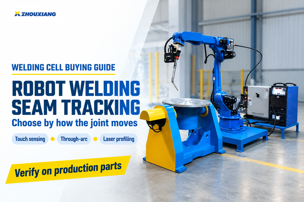
While some maintenance teams use stick electrodes to resurface conveyor rollers, high volume beam fabrication relies on automated H-beam welding line systems. Facilities aiming to increase throughput of their structural assembly can review our heavy-duty H-beam assembly and submerged arc welding workflow. Shops can also use robotic welding seam tracking for repeatable overlay passes for repetitive wear plates.
Commercial Cross-Reference, Electrode Diameters, and Procurement Checklist
Procurement teams frequently encounter proprietary trade names from Lincoln Electric, Stoody, ESAB, and Hobart Brothers rather than bare AWS A5.13 codes. Suppliers such as Postle Industries and Hardface Technologies use their own proprietary names as well. Relying on AWS A5.13 specifications and alloy content, or on cross-references provided by the commercial welding products, can help prevent purchase of an incompatible grade from Airgas and other suppliers.
There is an important scope boundary of the equipment to be manufactured. Wuxi Zhouxiang Complete Set of Welding Equipment Co., Ltd. (founded in 1991) manufactures heavy industrial welding equipment, H-beam production lines, CNC cutting machines, and rotary welding positioners. We do not manufacture or sell consumable hardfacing stick electrodes. The cross-reference table provided is for the independent engineering assessment of maintenance and fabrication buyers.
| Metallurgical Category & AWS A5.13 Class | Lincoln Electric (Wearshield) | Stoody (ESAB Group) | ESAB (OK Weartrode) | Hobart Brothers (Hardalloy / McKay) | Procurement Packaging & Pricing Structure |
|---|---|---|---|---|---|
| Machinable Low-Alloy Buildup (EFe-1, ~28–35 HRC) | Wearshield BU / BU-30 | Stoody Build-Up LH | OK Weartrode 30 | Hardalloy 32 | 10–50 lb master cartons; lowest alloy tier (requires vendor quote) |
| Austenitic Manganese Impact (EFeMn-A / Cr, 18→50 HRC) | Wearshield Mangjet / Frogmang | Stoody Dynamang / Nicromang | OK 86.08 / Mangrode | Hardalloy 118 (Mn-Ni) | 5–10 lb hermetically sealed cans or 50 lb boxes (requires vendor quote) |
| Martensitic Metal-to-Metal (EFe-2 to EFe-4, 45–55 HRC) | Wearshield MI | Stoody 1105 / Self-Hardening | OK Weartrode 50 | Tool-Alloy C / Hardalloy 58 | 10 lb tubes or 50 lb cartons; mid-tier alloy pricing (requires vendor quote) |
| High-Chromium Carbide Abrasion (EFeCr-A1A / A4, 56–62 HRC) | Wearshield ABR / Wearshield ME / 60 | Stoody 2134 / Stoody 31 / 35 | OK Weartrode 55 / 60 T | Hardalloy 140 / Hardalloy 148 | 5–10 lb tubes or 50 lb industrial packs; high-Cr tier (requires vendor quote) |
| Tubular Tungsten Carbide & Cobalt (EWC / ECoCr-A) | Wearshield TC / Cobalt grades | Stoody Borod / Castweld 6 | Stoody / Kennametal Stellite 6 | McKay Tube-Alloy WC grades | 1–5 lb specialty tubes; tungsten/cobalt surcharge tier (requires vendor quote) |
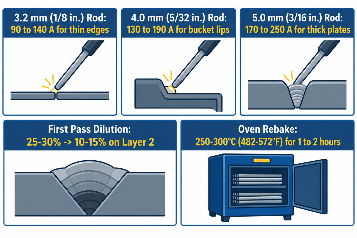
Choosing the correct stick electrode diameter and current window prevents excessive first layer dilution. The first layer experiences 25% to 30% base-metal dilution, while the second layer drops to 10% to 15% dilution. Running stick electrodes at the lower half of the amperage range retains greater carbide density.
- For 3.2 mm (1/8 in.) diameter electrodes, run 90 to 140 A (DCEP or AC). This diameter stick electrode is good for thin edges, such as those on auger flights and heat-sensitive Mn steel skip welds.
- For 4.0 mm (5/32 in.) diameter electrodes, run 130 to 190 A (DCEP or AC). This size is used for bucket lips and chute liners, and for multi-pass roller build-up.
- For 5.0 mm (3/16 in.) diameter electrodes, run 170 to 250 A (DCEP or AC). This heavy rod is built for high-deposition flat surfacing on heavy crusher jaws and thick wear plates.
Moisture in the shop air causes low-hydrogen buildup and martensitic rods to quickly absorb humidity. Moisture-sensitive electrodes should be rebaked at 250°C to 300°C (482°F to 572°F) for 1 to 2 hours before mild steel welding. Make sure your shop is equipped with essential arc welding cables, electrode holders, and drying ovens rated for continuous duty cycles.
Hardfacing & Workpiece Positioning RFQ Specification Checklist
Use this engineering checklist when seeking quotes from electrode distributors or specifying rotary positioning and automated beam welding machinery:
| Specification Parameter | Required Engineering Input | Why It Prevents Shop-Floor Failure |
|---|---|---|
| 1. Parent Metal Grade & Thickness | Exact steel spec (e.g., AISI 1045, 12% Hadfield Mn, AR400, Gray Cast Iron) + thickness (mm) | Determines whether 150–300°C preheat or a strict <260°C (500°F) interpass limit applies |
| 2. Primary & Secondary Wear Mode | Sliding silica abrasion, high-stress rock gouging, heavy impact, metal-to-metal, or >538°C heat | Prevents putting brittle 60 HRC carbides on impact hammers or unhardened Mn rods in sand chutes |
| 3. Required Dimensional Buildup Depth | Total missing metal depth (mm) prior to applying the 1–2 layer (3–6 mm) hardfacing cap | Specifies exact quantity of EFe-1 buildup and E309L buffer rods so welders do not over-stack cap passes |
| 4. Electrode Diameter, Polarity & Pack Size | 3.2 mm, 4.0 mm, or 5.0 mm; DCEP vs. AC transformer compatibility; hermetically sealed cans | Matches shop power source output and prevents moisture pickup in humid maintenance bays |
| 5. Workpiece Weight & Flat-Positioning Need | Component weight (kg/tons), rotation diameter, and whether automated SAW/FCAW lines are needed | Sizes L-type rotary welding positioners to hold fluid hardfacing puddles in the 1G flat position |
Frequently Asked Questions
Should I use 6013 or 7018 as a base pass before hardfacing mild steel?
When laying a base pass beneath hardfacing overlays on carbon steel, always choose low-hydrogen AWS E7018 (15 to 22 HRC) over rutile E6013. E6013 increases diffusible hydrogen and shallows the fusion zone, which, in conjunction with underbead cracks, increases the risk of cracking when the chromium carbide caps cool and contract. However, if the component faces heavy rolling contact or severe pounding loads, E7018 should be replaced by a dedicated AWS EFe-1 low-alloy buildup electrode (28 to 35 HRC). A dedicated buildup alloy resists subsurface plastic mushrooming and delaminating of the wear cap.
Must parts be preheated before applying hardfacing welding rods?
Preheat requirements range from 20°C room temperature for mild steel up to 149°C–316°C (300°F–600°F) for medium- and high-carbon steels. Plain low-carbon mild steel below 0.25% carbon only needs to be warm and dry above 20°C. Medium-carbon, high-carbon, and low-alloy steels (0.30% to 0.55% C) require 149°C to 316°C preheat to prevent heat-affected zone cracking. By contrast, 11% to 14% Hadfield austenitic manganese steel must never be preheated and must stay below 260°C (500°F) interpass.
Can cast iron components be hardfaced with standard stick electrodes?
Yes, Gray and ductile cast iron parts (2.5% to 4.0% carbon) can be hardfaced for low-impact sliding abrasion, with strict thermal control. Because cast iron contains free graphite flakes or nodules, welding directly onto cold castings causes carbon pickup and forms brittle white iron along the fusion boundary. Apply short 25 to 40 mm stringer passes with light peening between passes to relieve tensile shrinkage stress. For non-structural cast iron chutes and liner plates where cross-checking is acceptable, high-chromium carbide electrodes can be deposited directly over a preheated casting.
Why do chromium carbide hardfacing welds develop transverse cracks as they cool?
Transverse relief checks spaced every 10 to 19 mm (3/8 to 3/4 in.) across high-chromium carbide beads (55 to 63 HRC) are beneficial stress-relief fractures. As the hypereutectic carbide matrix cools, fine cross-checks release internal tensile shrinkage stress so the overlay does not peel off along the fusion boundary.
What welding polarity and current settings do stick hardfacing electrodes use?
Covered hardfacing stick electrodes run on DCEP or AC at 90 to 140 A for 3.2 mm rods and 130 to 190 A for 4.0 mm rods.
How many layers of hardfacing welding rod can you apply without spalling?
High-chromium carbide (AWS EFeCr-A1) and tubular tungsten carbide (EWC) cap rods are restricted to a maximum of 1 to 2 layers (total of 3 to 6 mm) to prevent shrinkage spalling. Martensitic steel electrodes (EFe-2 to EFe-4) permit 2 to 3 layers, while buildup (EFe-1) and manganese (EFeMn-A) rods are unrestricted.
References & Sources
- American Welding Society (AWS): A5G Subcommittee Scope: AWS A5.13/A5.13M:2024 Specification for Surfacing Electrodes for Shielded Metal Arc Welding
- American Welding Society (AWS Welding Digest, Oct 2024): Hardfacing Tips: A Best Weld Overlay Practice by Guy Chouinard
- AWS A5.13/A5.13M Surfacing Electrode Chemical Composition and Classification Tables
- The Fabricator (FMA Communications): SMAW Hardfacing Electrode Basics: Deposition Rates, Dilution, and Alloy Selection
- The Fabricator: A Primer on Hardfacing Metal: Microstructure vs. Bulk Rockwell Hardness
- Metals (MDPI Peer-Reviewed Journal, 2023): Comparative Dilution, Microstructure, and Wear Behavior of Hardfacing Overlays
- United States Patent and Trademark Office (USPTO): US9475154B2: High-Boron Hardfacing Welding Electrode
- United States Patent and Trademark Office (USPTO): US4923511A: Composite Tubular Tungsten Carbide Hardfacing Rod