Updated November 2026 · Structural Steel & Pipeline Welding Quality Reference
In fabrication, industrial arc strike welding defects occur outside the weld joint. They happen when a welding electrode, live nozzle, or loose ground clamp touches bare steel. Materials Joining Innovation Centre (MaJIC) metallurgical guidance states that a quick flash can bring steel to approximately 2,500 degrees F. The surrounding cold plate quickly quenches and cools steel to 500 degrees F in a matter of seconds. As defined in AWS D1.1/D1.1M:2025-AMD1, accidental blemishes must be ground to a smooth contour and checked for soundness. Pipeline rules under 49 CFR § 195.226 mandate either full notch grinding within pipe wall tolerances or full cylinder removal.
Even small defects from unstable initiation, or lack of proper arc control, require subsurface verification. A superficial surface polish rarely eliminates the underlying phase change. Field hardness checks are detailed on the American Welding Society Inspection & Qualification Forum. They show that a flush ground scar can read below RC 18 at a smeared surface. An RC 34 to 42 martensitic core, however, is still present about 1/32 of an inch beneath the surface. To completely remove that hardened layer requires controlled blend grinding and chemical temper etching with ammonium persulfate or nital. Following that, inspectors conduct magnetic particle testing and ultrasonic wall thickness verification.
Quick Specs: Arc Strike Welding Defects & Code Disposition Thresholds
| Thermal Quench Cycle on Cold Steel | Heats above 2,500 °F and self-quenches below 500 °F in seconds (MaJIC / Canadian Metalworking) |
| Measured Subsurface & Weld Hardness | RC 34 to 42 subsurface hard spot (AWS CWI field data); 500 to 751 HV10 peak on S355 steel (NIH PMC11084295) |
| Typical Phase-Change Excavation Depth | Approximately 1/32 inch (0.8 mm) minimum grind depth polished to 120 Grit before chemical etching |
| Chemical Temper-Etch Formulations | 20% ammonium persulfate / 80% water by weight at 120 to 150 °F (or 1:10 spray at 60 °F); 3% to 5% Nital for 10 s |
| Maximum Pipeline Grinding Depth | Up to 12.5% of nominal wall thickness (87.5% remaining wall floor per manufacturing tolerance & 49 CFR 195.226) |
| Governing Standards (2025–2026) | AWS D1.1/D1.1M:2025-AMD1, BS EN ISO 5817 (Ref. 601), 49 CFR § 195.226, 29 CFR § 1910.254, AMS 2700 |
What Are Arc Strike Welding Defects? Rapid-Quench Metallurgy and Failure Analysis
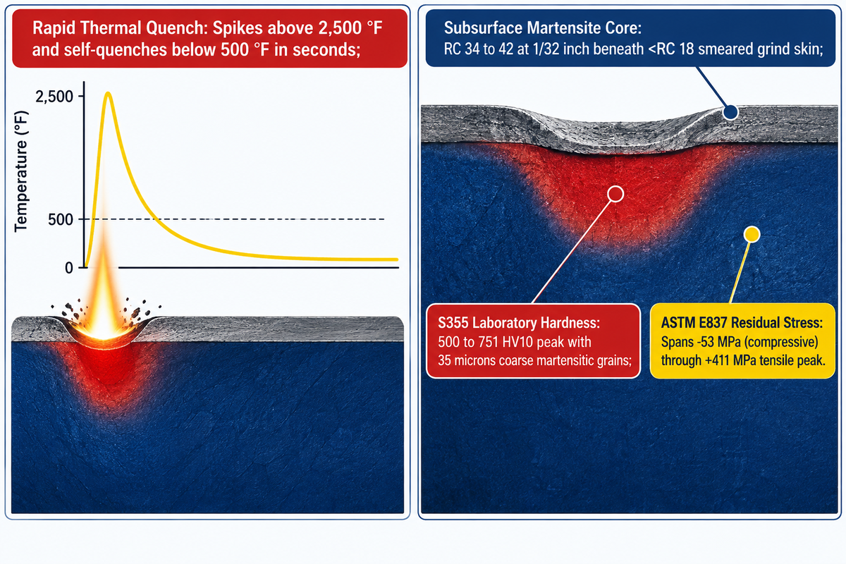
An arc strike is a localized remelted crater and hardened heat affected zone formed outside the weld joint. According to the MaJIC data in Canadian Metalworking, the spot spikes above 2,500 degrees F and cools below 500 degrees F in seconds. On S355 steel in NIH study PMC11084295, rapid quenching reaches between 500 to 751 HV10.
Some shop employees explain stray arc marks as shallow cosmetic scuffs that shot blasting or primer will cover. Anything that causes a drag line can result in an accidental strike. It melts a shallow molten pool while delivering near-zero total heat input into a massive cold workpiece. Cold workpiece acts as an immediate heat sink and alters structure of the base metal. This rapid heating and cooling locks carbon in a distorted body-centered tetragonal crystal lattice. The quench produces untempered martensite. It also leaves residual stresses spanning −53 MPa (compressive) through +411 MPa (with peak tensile residual stresses between +300 and +411 MPa) in ASTM E837 hole-drilling tests on round-electrode S355 specimens.
In formal failure analysis, every unremoved arc strike acts as both a metallurgical hard spot and a geometric stress notch. During loading and unloading of bridge traffic, the microfissures initiated on the hardened crater rim propagate along the bridge underdeck and can mix with other types of stress corrosion cracking, such as cracks. Internal pipeline pressure fluctuations drive the same crack growth. Fabricators assessing hydrogen-induced cold cracking in structural welds consider the three triggers of arc strike: untempered martensite, localized tensile stress and trapped hydrogen, either from saturated flux or grease.
Why Does a Stray Arc on Steel Form Untempered Martensite and Microcracks?
A stray arc creates an untempered martensite because millisecond arc contact melts a shallow pool without preheating the plate. That cold mass drives an extreme cooling rate. Carbon can’t diffuse into soft ferrite and pearlite. Under round 4.00 mm stick electrodes on 10 mm S355 steel, NIH PMC11084295 documents coarse martensitic crystal grains of 35 microns or wider.
During normal multipass welding within a bevel groove, sustained heat input slows cooling and subsequent passes temper earlier beads. A strike outside the groove receives zero tempering passes. This is covered in the Lake Washington Institute of Technology pipe welding curriculum. Isolated martensitic islands contract while cooling and create crater cracks or underbead microvoids. AWS certified welding inspectors conducted guided-bend demonstrations on 3/8 inch and 1/2 inch flat bar. They performed welding with E6010, E7018, or MIG wire and buffed the steel smooth before the demonstration. Even after surface buffing, the specimen snapped open across the strike during bending.
Common Causes of Arc Strikes vs. Arc Blow, Spatter, and Weld Undercut
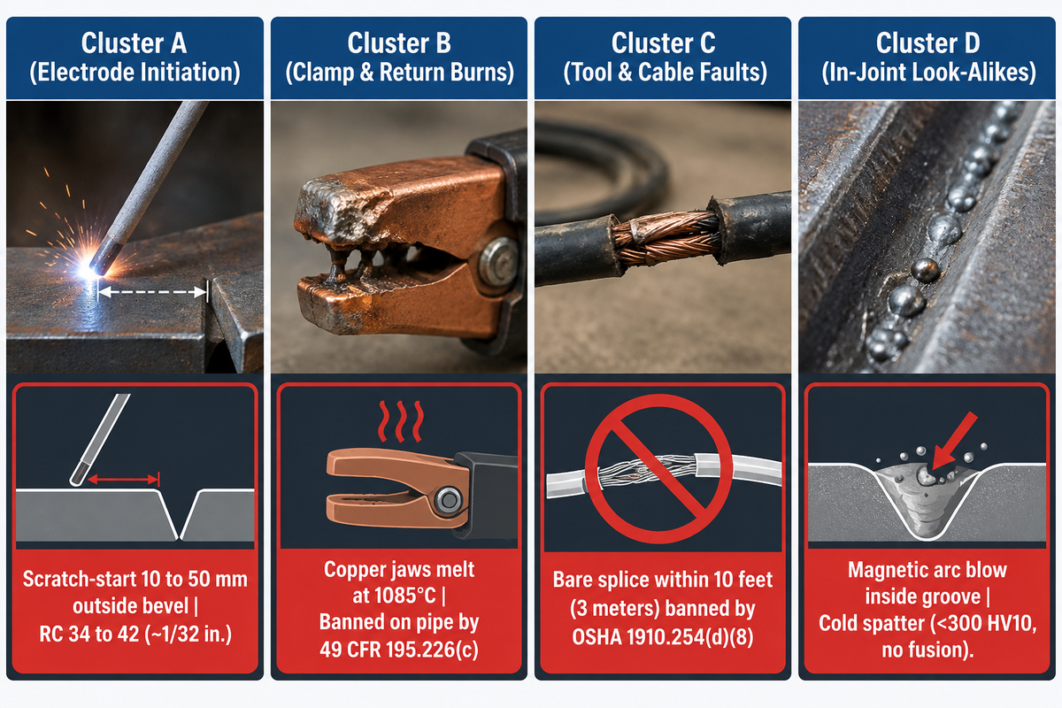
Four pathways cause Parent-Metal arc strike. Scratch starts caused by electrode outside the groove, contact against steel, and arcing across a loose ground clamp are three of the pathways. The fourth pathway is current leakage through cable splices banned within 10 feet (3 meters) by OSHA 29 CFR 1910.254(d)(8). True strikes of Parent Metal fuse it, unlike Cold Spatter.
Job-site inspections stall when welders misinterpret this type of defect with in-groove irregularities in the weld. To resolve the occurrence of arc strikes, understand that Parent-metal fusion is different from loose spatter. Loose weld spatter globules chill against mill scale without deep fusion, and if an errant arc root is present at the point of impact, it will fuse to the base metal. Weld-toe undercut leaves a continuous linear groove along the fused edge, rather than a crater, along the fusion boundary. Linear toe gouges and electrode contact marks are different and can be determined by inspection of the weld-toe undercut causes and groove measurement.
While under service tension, those localized high hardness lenses function as extremely dangerous crack initiation points and primary crack initiation sites. Return-circuit arcing is equally as dangerous. A weak spring clamp is often found over rust, paint, or adherent spatter on a 16 inch pipeline or heavy girder. Welding current then jumps the air gap and melts the clamp into the workpiece. Copper-alloy jaws melt at about 1085°C and have been known to penetrate the grain boundaries of steel, thereby causing embrittlement cracking. OSHA’s 29 CFR 1910.254(c)(2)(iii) also forbids the use of chains, wire ropes, cranes, hoists, or elevators to transport welding current.
What are common causes of arc blows?
Common causes of magnetic arc blow include an asymmetrical magnetic field near plate ends, residual magnetism in steel pipe bevels, high direct-current amperage, and poor work-lead placement. Unlike an external arc strike that quenches the parent metal outside the joint, arc blow deflects the active welding arc inside the groove and causes lack of fusion.
Arc blow happens during direct-current welding near plate ends, deep root openings and magnetized pipe bevels. Welders counter arc blow by shortening the arc length and angling the electrode toward the deflection. They may also place the work-lead in the opposite direction from the weld. As a last resort, welders may use alternating current within the 80 volts manual AC and 100 volts DC limits of OSHA 29 CFR 1910.254(b)(3). None of the magnetic adjustments allow for a stray strike on the bare parent steel outside the bevel.
| Defect Cluster | Specific Discontinuity Type | Where It Appears | Subsurface HAZ & Hardness Impact | Required Shop Disposition |
|---|---|---|---|---|
| Cluster A: Electrode Initiation Errors | 1. Scratch-Start SMAW Strike | 10 to 50 mm outside bevel edge | RC 34 to 42 martensite (~1/32 in. deep) | Grind ~1/32 in., 120 Grit polish, acid etch + MT |
| Cluster A: Electrode Initiation Errors | 2. GTAW Tungsten Touch Strike | Adjacent flange or tube wall | Shallow crater + tungsten inclusion risk | Blend grind smooth, PT or RT verify inclusion removal |
| Cluster A: Electrode Initiation Errors | 3. Unconsumed MIG Wire Poke | Nozzle clearance zone near web | Localized 500 to 650 HV10 quench spot | Feather grind 1:4 slope, verify soundness by MT |
| Cluster B: Return-Current & Clamp Burns | 4. Loose Spring-Clamp Arc Burn | Flange tip or pipe body clamp seat | Deep HAZ + copper LME intergranular cracks | Grind out notch, 20% persulfate etch, UT wall check |
| Cluster B: Return-Current & Clamp Burns | 5. Welded-On Ground Tab Burn | Pipe exterior (banned by 49 CFR 195.226c) | Full-thickness HAZ & high residual stress | Prohibited on liquid pipelines; requires cutout or repair |
| Cluster B: Return-Current & Clamp Burns | 6. Crane / Hoist Chain Stray Arc | Lifting lug & chain contact links | Embrittles load chain (banned by 1910.254c2iii) | Quarantine sling immediately; grind & MT lug surface |
| Cluster C: Tool & Cable Faults | 7. Uninsulated Stinger Lay-Down | Deck plate, scaffold, or boiler tube | Multiple cluster craters (<1 week boiler tube leak) | Enforce 1910.254(d)(7) holder cradle; grind + etch |
| Cluster C: Tool & Cable Faults | 8. Bare Cable Splice Flash (<10 ft) | Beam flange edge rubbed by lead | Linear drag strike + RC 34 to 42 hardened track | Replace cable per 1910.254(d)(8)-(9); blend grind |
| Cluster D: In-Joint Look-Alike Defects | 9. Magnetic Arc Blow Wander | Inside weld groove & root of the weld | Normal weld HAZ; causes lack of fusion / porosity | Adjust ground lead & arc length; gouge if unfused |
| Cluster D: In-Joint Look-Alike Defects | 10. Cold Adherent Weld Spatter | 5 to 100 mm beside weld bead | No base-metal fusion (<300 HV10 parent steel) | Chip or light flap-disc dress before blast cleaning |
Arc Strike Acceptance Criteria: AWS D1.1:2025, ISO 5817, and API 1104 Compared
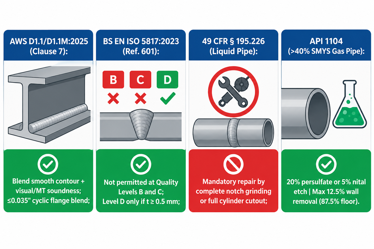
There are two categories of governing codes: conditional blend-grinding standards and zero-tolerance standards. AWS D1.1/D1.1M:2025-AMD1 and CSA W59 require blemishes or cracks from arc strikes to be blended to a smooth profile and verified for metal soundness. According to ISO 5817:2023 (Ref. 601, discussed in TWI Job Knowledge 38 Quality Levels), stray arc is not acceptable at Quality Levels B and C.
Quality engineers frequently over-reject structural steel beams. Social-media extracts incorrectly state that AWS D1.1 demands an immediate weld buildup or beam scrapping for any stray mark. In practice, for girders under a static or cyclic loading load case, AWS D1.1 workmanship rules apply. Shop crews must avoid stray strikes outside permanent joints. Any accidental craters or surface cracks require smooth contour blending and soundness inspection. The ANSI Technical Review of AWS D1.1:2025 (23rd Edition) states that world crude steel output was 1,884 million tonnes in 2024. The 2025 edition expanded provisions for magnetic particle testing (MT) and penetrant testing (PT) to evaluate repaired surfaces.
This lookup matrix, used by quality personnel to prevent cross-code confusion, compares the rules in AWS D1.1:2025, ISO 5817:2023 reference 601 Levels B/C/D, API 1104 and 49 CFR 192 & 195 temper-etch mandates, and ASME B31.3/VIII design-thickness floors.
| Code / Standard Tier | Governing Clause / Ref. | Initial As-Struck Status | Mandatory Post-Grind Test | Thickness Limit & Escalation Trigger |
|---|---|---|---|---|
| 1. AWS D1.1/D1.1M:2025 (Static Steel) | Clause 7 Workmanship | Avoid outside permanent welds | Visual soundness + MT when specified | Smooth contour within mill/design section tolerance; else qualified WPS repair |
| 2. AWS D1.1:2025 / CSA W59 (Cyclic) | Cyclic Load Provisions | Rejectable crack initiator | Mandatory magnetic particle inspection (MT) | ≤0.035″ bridge flange blend with engineer/DOT RT or MT sign-off |
| 3. BS EN ISO 5817:2023 Level B | Ref. 601 (Item 1.22 Stray Arc) | Not permitted (Stringent quality) | Grind out + MT/PT + hardness/etch per ITP | Zero parent-metal impairment permitted; requires formal NCR disposition |
| 4. BS EN ISO 5817:2023 Level C | Ref. 601 (Item 1.22 Stray Arc) | Not permitted (Intermediate quality) | Grind smooth + surface NDE verification | Remaining thickness must stay at or above design calculation floor |
| 5. BS EN ISO 5817:2023 Level D | Ref. 601 (Item 1.22, t ≥ 0.5 mm) | Permitted if properties unaffected | Visual check for absence of crater cracks | Disqualified on quench-hardening alloy steels where HAZ turns brittle |
| 6. 49 CFR § 195.226 (Liquid Pipe) | Subpart D § 195.226(a)-(c) | Mandatory repair of every arc burn | Complete notch removal + wall measurement | Below pipe spec minimum wall tolerance triggers full pipe cylinder cutout |
| 7. API 1104 / High-Pressure Gas Pipe | Arc Burns (>40% SMYS service) | Rejectable metallurgical notch | 20% ammonium persulfate or 5% nital etch | Max 12.5% wall removal (87.5% nominal wall floor); weld repair prohibited |
| 8. ASME B31.1 Power Piping | Arc Strike Repair Rules | Remove all cracks & blemishes | PT or MT mandatory on alloy steel piping | Water-wall boiler tubes left unground can burn through in <1 week |
| 9. NYS Bridge / DOT Steel Manual | Bridge Girder Arc Strike Removal | Rejectable fracture-critical flaw | Portable hardness test (<RC 18) + MT/RT | Grind past RC 34–42 subsurface zone (~1/32 in.) until parent hardness returns |
| 10. AWS D1.6 / AMS 2700 Stainless | Stainless Surface & Passivation | Heat-tint oxide & microfissure risk | Liquid penetrant testing (PT) + visual tint check | Remove straw-to-purple oxide to bare metal before nitric/citric passivation |
How to Inspect Arc Strikes: Visual, Magnetic Particle, Penetrant, and Acid Etching
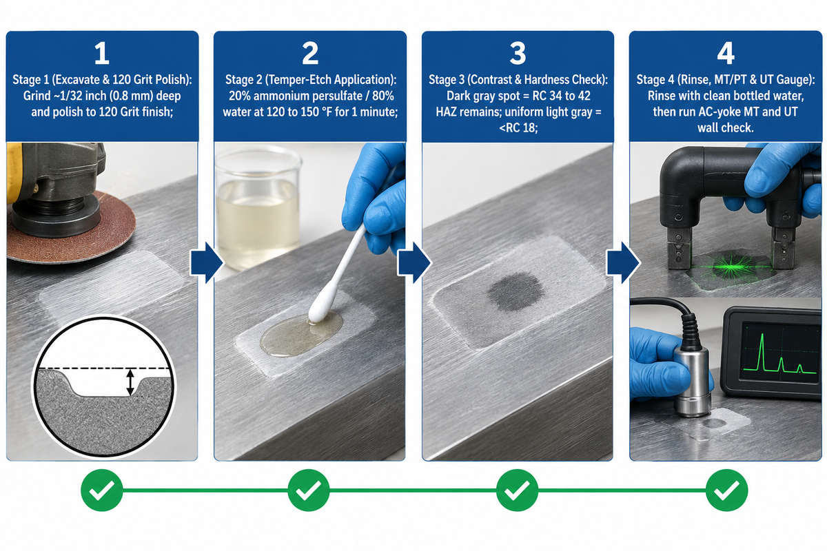
Verification of complete arc strikes requires two inspection layers. The first is chemical temper etching. For ammonium persulfate, the standard temperatures are 120 to 150 degrees F (49 to 66 degrees C), and the standard etchant time is 1 minute. Two etchants are commonly used: 1) 20% ammonium persulfate with 80% water, and 2) 5% nital. Second, penetrant or magnetic particle testing proves zero surface cracks remain.
“(a) Each arc burn must be repaired. (b) An arc burn may be repaired by completely removing the notch by grinding… If a notch is not repairable by grinding, a cylinder of the pipe containing the entire notch must be removed. (c) A ground may not be welded to the pipe or fitting that is being welded.”
A dangerous shop misconception is assuming that a clean magnetic particle inspection after coarse-wheel grinding proves the arc burn is gone. As senior AWS CWI inspectors indicate on the AWS Forum, coarse abrasive wheels, in the process of grinding, smear ductile metal across microcracks, and leave a decarburized skin on the surface. Portable hardness yields RC 34 to 42 after the grinding process. Only after grinding roughly 1/32 inch (0.8 mm) deep and polishing with 120 Grit sandpaper does the reading drop back below RC 18.
For laboratory metallography on S355 steel, NIH PMC11084295 specifies polishing up to P2500 grit and etching with 3% Nital for 10 seconds. Technicians then measure Vickers hardness under a 10 kg load for 10 to 15 seconds on a 0.5 mm grid per EN ISO 9015-1. In the field, pipeline and bridge inspectors mix 1 gram of granular ammonium persulfate with 4 grams of pure water. That mixture equals a 20% to 80% weight ratio, while bridge crews also use a 1:10 spray bottle at 60 degrees F. Swabbed onto warm carbon steel (120 to 150 degrees F), any unremoved HAZ turns dark gray against light-gray base metal within 1 minute. When deep volumetric verification is required on thick repaired bridge flanges, teams pair surface etching with volumetric radiographic weld inspection.
Does Magnetic Particle or Acid Etching Confirm Complete Arc Burn Removal?
Macro-chemical etching, either with aqueous ammonium persulfate or with nitric-alcohol nital, verifies complete removal of the heat-affected zone on carbon steel. Magnetic particle testing can only reveal surface or near-surface cracks. Passing magnetic particle or dye penetrant inspection, without chemical etching or hardness testing, can leave a brittle RC 34 to 42 martensitic island.
Ammonium persulfate etching has one strict metallurgical boundary. The solution doesn’t act on austenitic stainless steels. On carbon and high-strength low-alloy steels working above 40% SMYS, inspectors polish the ground cavity to a 120 Grit finish. The inspectors keep the surface wet with ammonium persulfate for 60 seconds to allow any gray phase-change contrast to develop. They then rinse with clean, bottled water as opposed to an oily shop rag. They then perform AC-yoke magnetic particle testing and ultrasonic thickness gauging.
Grinding vs. Qualified Weld Repair: Wall-Thickness Math and Disposition Rules
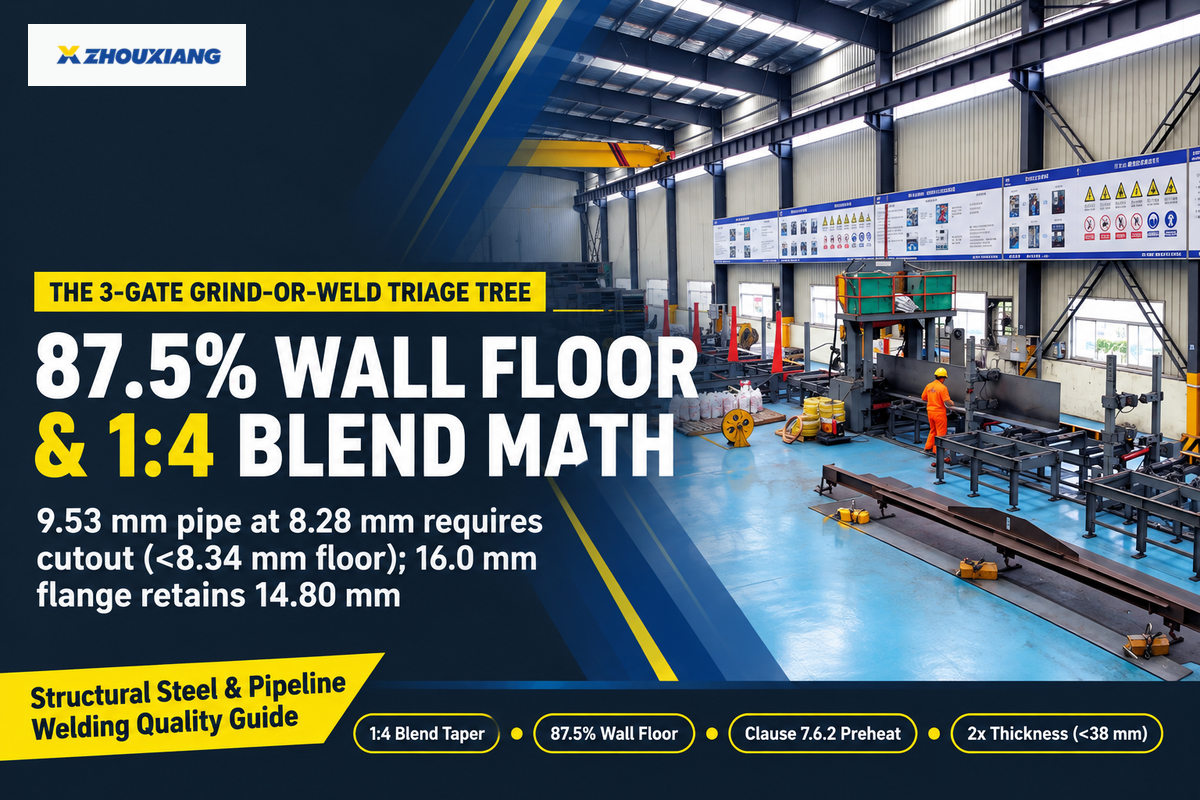
When excavating the 1/32 inch (0.8 mm) phase-change zone, engineers often rely on blend grinding over weld repairs to obtain a clean acid etch and eliminate magnetic particle crack indications. The remaining wall thickness must be at or above the specification minimum, e.g. 87.5% of the nominal pipe wall (12.5% wall removal).
To standardize field decisions across structural girders and pressure pipe, quality managers apply The 3-Gate Grind-or-Weld Triage Tree:
- At Gate 1 (Progressive Excavation and 120-Grit Polish), perform a series of light passes using a flapper disc on a 4 inch grinder to grind off the surface crater. This removes coarse-wheel friction re-hardening, and allows for excavation of about 1/32 inch (0.8 mm) to polish the contour.
- At Gate 2 (Chemical Temper-Etch and NDE Soundness Gate), swab the polished cavity with an ammonium persulfate or nital etchant. If a dark gray spot or portable hardness reading of RC 34 to 42 is observed, perform Gate 1 again. If an even, light gray color and RC <18 are observed, rinse with water to remove etchant, and evaluate for cracks by magnetic particle or liquid penetrant testing.
- At Gate 3 (Remaining Wall Thickness and Code Disposition Gate), if the ultrasonic thickness gauge measurement at the ground low point indicates the remaining wall is within the 12.5% pipe wall tolerance, release the part. If grinding resulted in wall thinning to less than the minimum, perform a cylinder cut-out under 49 CFR 195.226(b) or a qualified low-hydrogen weld repair in accordance with AWS D1.1:2025.
Using 1:4 blend-taper math, a 1.25 mm excavation on 9.53 mm API 5L pipe leaves 8.28 mm (< 8.34 mm, 87.5% wall floor), while a 16.0 mm ASTM A572 H-beam flange retains 14.80 mm. Because 8.28 mm falls below the 8.34 mm floor, the pipe requires a 49 CFR 195.226(b) cylinder cutout, whereas the 14.80 mm flange (faired over a 4.80 mm radius) passes with MT under AWS D1.1:2025. Deeper structural gouges may require weld repair under AWS D1.1:2025 Clause 7.6.2 preheat rules in The Fabricator (quoting AISC Senior Engineer Tom Schlafly). Under Clause 7.6.2, steel plates under 38 mm require preheating across twice the base metal thickness (2 × 16.0 mm = 32.0 mm). Plates 38 mm and thicker require heating a distance at least equal to the plate thickness and no less than 3 inches (75 mm) in all directions from the repair.
Can You Weld Directly Over an Arc Strike Without Grinding It Out First?
No, you must never place a quick touch-up weld bead directly over an unground arc strike outside the joint. Only an in-groove strike that will eventually be fully remelted by the scheduled root or filler pass is allowed to be welded over after checking for crater cracks.
A short cold weld bead traps pre-existing shrinkage cracks and creates an untempered heat affected zone. When structural welding is required, fabricators must first fully grind the brittle martensitic lens and remove cracks by MT. Welders then follow controlled welding preheat procedures under a low-hydrogen Welding Procedure Specification (WPS).
- Grind 1/32” deep, and polish to 120 Grit before etching.
- Test to see if the dark-gray HAZ has been removed with ammonium persulfate or nital etchant.
- MT/PT and UT must be performed to check for surface cracks and verify that the remaining wall has not been reduced below 87.5% of the nominal wall thickness.
- It can’t be trusted that a first-pass flush grind left an RC 18 smeared surface. The integrity of the wall must always be verified by a subsurface check (RC 34-42).
- A cold E7018 or MIG tack should never be placed over an external parent-metal arc crater to cover the depression.
- Ammonium persulfate should never be used on austenitic stainless steel, nor should etched carbon steel be wiped with an oily shop rag.
Alloy Sensitivity: Mild Carbon, Quenched-and-Tempered, Stainless, and Duplex Steels
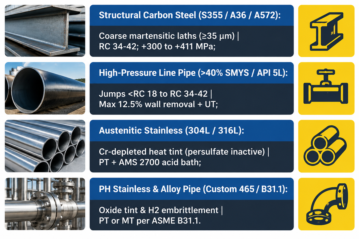
Arc-strike damage changes from martensitic cracking on carbon and alloy steel to passive film erosion on stainless alloy. In NIH PMC11084295, non-alloyed S355 structural steel loses yield strength Rp0.2 above 300 °C and falls sharply by 600 °C. Rapid cooling then produces tensile residual stresses in the range +300 to +411 MPa and 500 to 751 HV10 hardness.
Higher-carbon and quenched and tempered grades react even more violently because elevated carbon equivalent values lead to full untempered martensite transformation at room temperature. High-carbon castings and heavy machinery frames demand the same preheat practices outlined in our guide to crack-control repair planning for brittle base metals. When an arc strike hits an ASME B31.1 alloy steel power pipe, magnetic particle or liquid penetrant inspection is mandated after blend grinding.
Austenitic stainless steels (304L and 316L) and precipitation-hardening grades (such as Custom 465) follow a completely different failure mechanism. Austenitic grades don’t transform to martensite. As a result, some shops leave stray arc marks on stainless. A stray arc not only removes the passive chromium oxide film, but also leaves oxide scales of different colors, e.g. straw, gold, blue, purple, and/or Fe metal. Per AMS 2700 passivation guidelines, soaking a heat-tinted stainless part directly in an acid bath does not clean scale or grease. Technicians must first degrease the surface and remove all heat tint down to bare shiny metal using iron-free abrasives.
| Base Alloy Family | Primary Microstructural Damage | Measured Hardness / Stress Signal | Required NDE & Etch Method | Mandatory Post-Grind Treatment |
|---|---|---|---|---|
| 1. Structural Carbon Steel (S355 / A36 / A572) | Coarse martensitic-bainitic laths (≥35 μm) | RC 34–42 subsurface; +300 to +411 MPa stress | 20% ammonium persulfate or 3% nital + MT | 120 Grit blend grind; Clause 7.6.2 preheat if welded |
| 2. High-Pressure Line Pipe (>40% SMYS / API 5L) | Untempered martensite notch & underbead voids | Hard spot jumps from <RC 18 to RC 34–42 | 20% persulfate or 5% nital + MT + UT thickness | Max 12.5% wall removal; full cylinder cutout if deeper |
| 3. Austenitic Stainless Steel (304L / 316L) | Cr-depleted heat tint & crater microfissures | Non-martensitic (persulfate etchant inactive) | Liquid penetrant testing (PT) + visual tint audit | Remove straw/purple oxide to bare metal + AMS 2700 acid bath |
| 4. High-Strength PH Stainless / Alloy (Custom 465 / B31.1) | Nanometric oxide tint + hydrogen embrittlement risk | High strength loss & stress-corrosion cracking | PT or MT per ASME B31.1 + oxide removal check | Degrease, mechanical oxide removal, A-A-A passivation + bake |
Arc Strike Rework Cost Breakdown: Blend Grinding + MPI vs. Weld Repair and Cutout
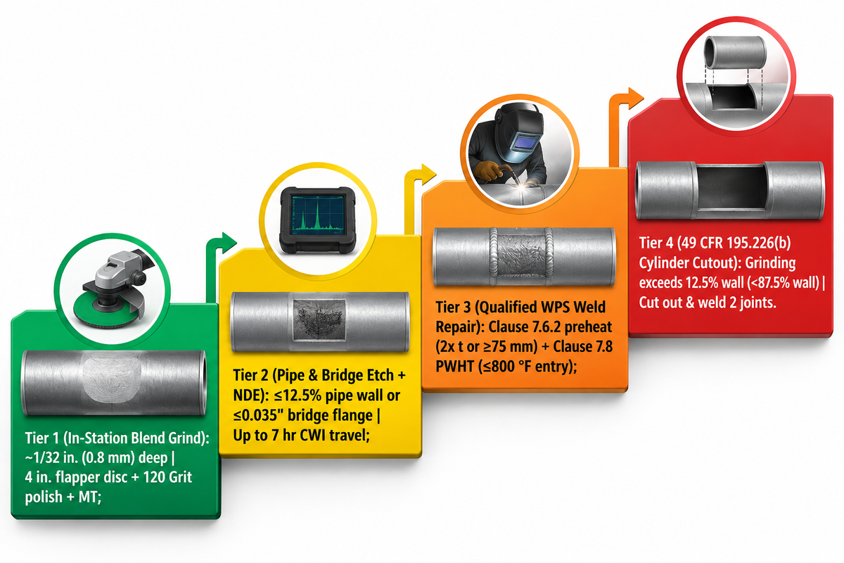
The total cost of rework for an arc strike scales directly with the extent of four operational drivers; the depth of excavation, the extent of preheat, NDT holds, and crew mobilization. As per the AWS CWI field reports and 49 CFR § 195.226, remediation begins with a 1/32 inch (0.8 mm) ‘in-station blend’ of grind, and escalates to a complete pipe section (cylinder) cutout.
The true cost driver is at what stage in the process an unintended electrode touch is caught. Catching an accidental electrode touch at the fit-up station requires only a 4 inch flapper-disc grind, a 120 grit polish, a 1 minute ammonium persulfate swab, and an in-house magnetic particle check. Missing the same strike at final inspection could lead to field or service mobilization. In one AWS CWI case, field carpenters “tack welded” temporary scupper braces to the bottom flange of a girder. The specialist drove 7 hours each way to do a 0.035 inch maximum flapper-disc blend and a 1:10 ammonium persulfate spray check at 60 degrees F. The crew captured all the chemical run-off on a barge and performed full Radiographic Testing (RT). Consolidated Edison boiler inspections showed the cost of missed strikes. Leaving an unground arc strike on an internal water wall tube resulted in it burning through in less than a week.
When the depth of excavation exceeds the 12.5% wall tolerance of the pipe or the section minimum, the schedule penalty is multiplied. As per AWS D1.1:2025 Clause 7.6.2, a qualified structural weld repair on plates less than 38 mm requires preheating across a distance of at least 2 times the plate thickness. Plates 38 mm and thicker require heating at least 1 times thickness with a 3 inch (75 mm) minimum. If Clause 7.8 post weld heat treatment (PWHT) is invoked, the weldment is put in a furnace under a written Heating and Cooling Procedure. According to the 2025 code, the maximum initial temperature of the furnace has been increased from 600 degrees F to 800 degrees F. For liquid pipelines governed by 49 CFR 195.226(b), an over-ground arc burn can’t be patched. Under eCFR Title 49 Section 195.226, grinding must not reduce remaining wall thickness below manufacturing tolerances. The pipeline must be depressurized, a full cylinder of pipe cut out and removed, and a weld pup joint placed and NDE run on the full circumference of the pipe.
| Rework Tier | Excavation & Geometry Trigger | Mandatory Execution Steps | QA Hold Points & NDE | Schedule & Commercial Impact |
|---|---|---|---|---|
| Tier 1: In-Station Structural Blend Grind | ~1/32 in. (0.8 mm) deep; section above minimum | 4 in. flapper disc smooth contour + 120 Grit polish | Visual soundness + MT on cyclically loaded girders | Cleared in-bay before blasting or priming |
| Tier 2: High-Pressure Pipe / Bridge Etch & NDE | ≤12.5% pipe wall or ≤0.035″ bridge flange loss | 120 Grit polish + 20% persulfate or 3%–5% nital etch | Etch witness (<RC 18) + MT/RT + UT wall thickness | Requires CWI/DOT witness (up to 7 hr travel in field cases) |
| Tier 3: Qualified Structural WPS Weld Repair | Excavation drops below structural section tolerance | Full HAZ removal + Clause 7.6.2 preheat (2x t or ≥75 mm) + low-H2 fill | Pre-weld MT, interpass temp log, post-weld MT/UT, Clause 7.8 PWHT (≤800 °F entry) | Multi-shift NCR hold; request shop quote by plate thickness |
| Tier 4: 49 CFR 195.226(b) Pipe Cylinder Cutout | Grinding exceeds 12.5% wall tolerance (<87.5% wall) | Cut out full pipe cylinder containing notch + weld 2 girth joints | Full-circumference RT/UT on replacement butt welds + pressure test | Highest cost tier; shuts down line stringing or hydrotest |
How to Prevent Arc Strikes in Shop Welding and Automated H-Beam Lines
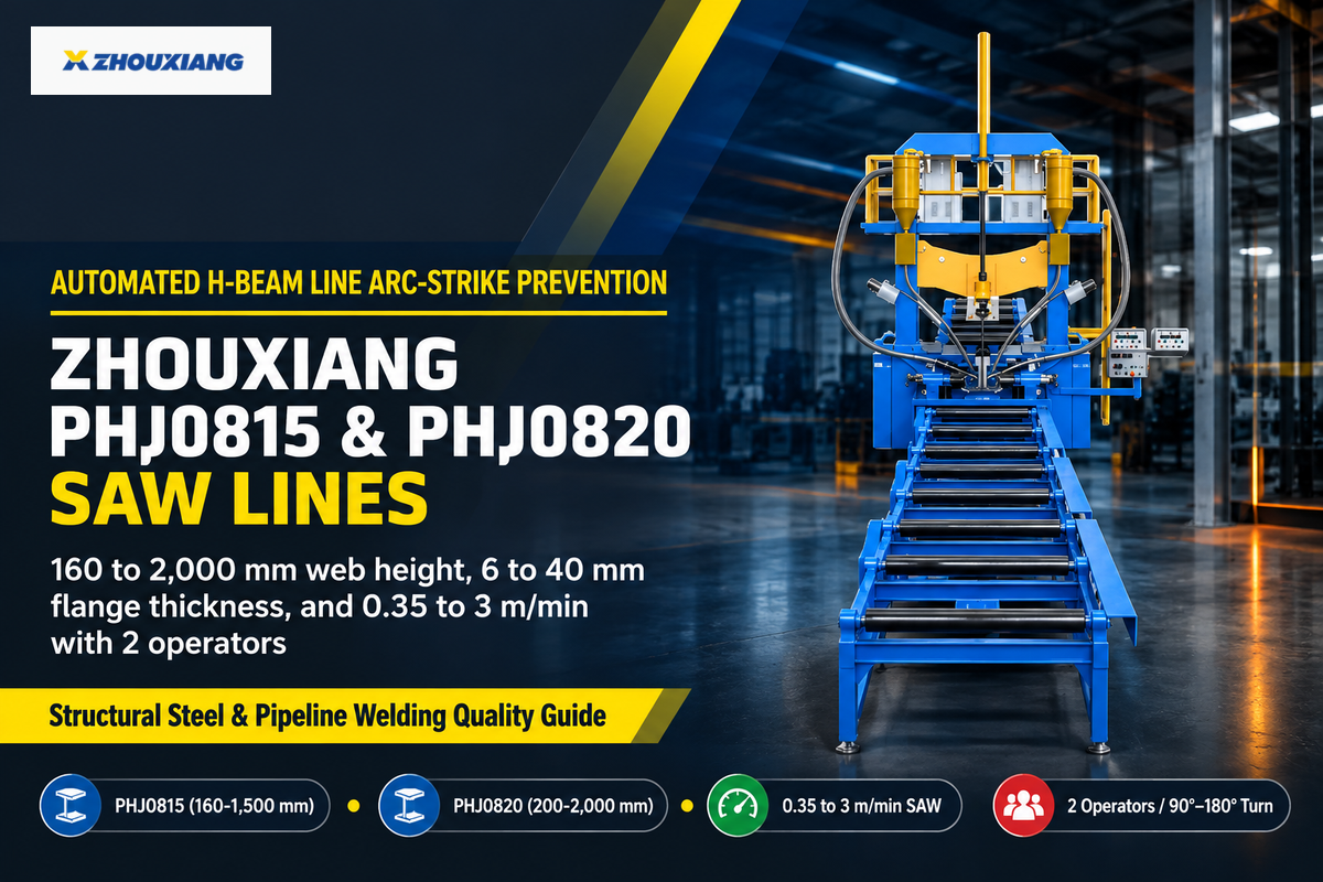
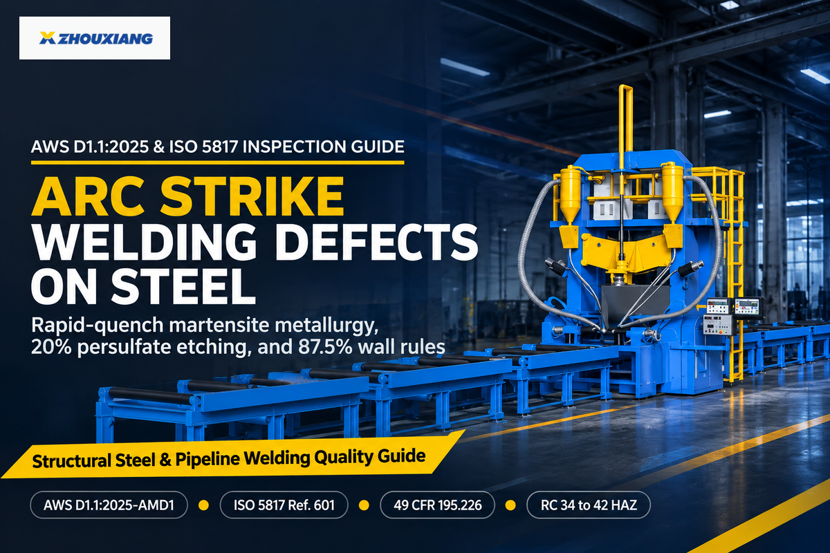
Fabrication shops prevent arc strikes by enforcing OSHA 29 CFR 1910.254 electrical controls at manual bays. In structural plants, manual web-to-flange tacking is being replaced by integrated hydraulic assembly, and submerged-arc beam welding lines. Across the two models, Zhouxiang’s PHJ0815 and PHJ0820 lines can process webs of 160 to 2000 mm with speeds of 0.35 to 3 m/min, with 2 operators.
(1910.254(d)(7)) Electrode holders. Electrode holders that are not in use must be placed to avoid electrical contact with people, conducting objects, fuel or compressed gas tanks. (1910.254(d)(8)) Electric shock. Cables with splices within 10 feet (3 m) of the holder must not be used. (1910.254(d)(9)(iii)) Cables with damaged insulation or bare conductors must be replaced.
At Manual shielded metal arc welding (SMAW) and GTAW stations, supervisors carry out The 5-Point Stray-Current Audit before each shift.
- For In-Groove or Run-On Tab Arc Initiation, welders are trained to initiate strictly within the weld groove or on a sacrificed run-on tab. The advancing weld metal then remelts the initiation point.
- For Screw-Down Ground Clamps on Bare Metal, replace weak spring clamps with high-torque screw clamps fastened to clean bare metal. Also remove adherent spatter from magnetic clamps in accordance with OSHA 1910.254(d)(2).
- For 10-Foot (3 m) Splice-Free Cable & Insulated Cradles, hang live stingers in insulated cradles per 1910.254(d)(7). Any leads showing bare wire or splices within 10 feet (3 m) of the holder are to be scrapped per 1910.254(d)(8)-(9).
- For Polarity & Return-Path Isolation, secure bond fixture return joints as stated in 1910.254(c)(2)(iv) and isolate cranes and wire ropes as stated in 1910.254(c)(2)(iii). Keep the cooling air within the 40 °C (104 °F) and 3,300 feet (1,005.8 m) machine envelope.
- For Mechanized Fixture Clamping & Automated Ignition, USPTO Patent Application US20060138090A1 pairs CPC B23K37/0435 mechanical clamps with B23K9/186 carriage submerged arc welding. That architecture cuts special machinery lead time from 12 to 15 months down to 3 to 6 months and eliminates manual stick tacking.
In heavy structural steel plants, most parent-metal arc strikes happen during manual H-beam web-to-flange fit-up tacking and overhead crane flipping. Plants can integrate assembly, submerged-arc welding, 90°/180° hydraulic turning, and straightening into an automated H-beam assembly and submerged-arc welding line. This removes manual stick tacking and crane-chain current paths from the web and flanges. Founded in 1991, Wuxi Zhouxiang Complete Set of Welding Equipment Co., Ltd. builds the PHJ0815 (web 160 to 1,500 mm, flange 6 to 25 mm) and PHJ0820 (web 200 to 2,000 mm, flange 8 to 40 mm). Both H-beam lines run at 0.35 to 3 m/min SAW speed with 2 operators in 2/3 less floor space. Mechanized web-flange alignment and 90/180-deg turning eliminate manual tacking strikes. Complex stiffeners and box-beam subassemblies benefit from programmable industrial welding robots. Robotic torch control keeps every arc start locked inside the programmed joint path.
Automated H-Beam Line Specification Comparison — Zhouxiang PHJ0815 vs. PHJ0820 (Published Factory Specs):
| Parameter | Zhouxiang PHJ0815 Line | Zhouxiang PHJ0820 Line | How It Prevents Stray Arc Strikes |
|---|---|---|---|
| Web Height Range | 160 to 1,500 mm | 200 to 2,000 mm | Hydraulic centering aligns web without manual pry-bar & stick tacking |
| Web Thickness Range | 6 to 16 mm | 6 to 30 mm | Continuous roller clamping prevents thin-web burn-through & stray flashes |
| Flange Width & Thickness | 150 to 800 mm width; 6 to 25 mm thick | 200 to 800 mm width; 8 to 40 mm thick | Dedicated machine ground shoes avoid flange-edge spring-clamp arc burns |
| Workpiece Length & SAW Speed | 6,000 to 15,000 mm; 0.35 to 3 m/min | 6,000 to 15,000 mm; 0.35 to 3 m/min | Single-arc double-wire SAW ignites under granular flux inside the fillet root |
| Crew Size, Footprint & Turning | 2 operators; 2/3 less floor space; 90°/180° turn | 2 operators; 2/3 less floor space; 90°/180° turn | Hydraulic turning replaces crane chains (OSHA 1910.254(c)(2)(iii) compliant) |
A stray arc strike on carbon or low-alloy steel forms an untempered martensitic lens. Subsurface hardness reaches RC 34 to 42 in field checks and 500 to 751 HV10 on S355 laboratory specimens. Crews must blend-grind roughly 1/32 inch deep to clear the hardened layer. Depending on whether AWS D1.1 structural rules or API 1104 and 49 CFR 195.226 pipeline limits apply, inspectors then verify soundness by visual, magnetic particle, or temper-etch checks. At scale, shops prevent strikes through run-on tabs, OSHA 1910.254 cable discipline, and automated H-beam lines.
Eliminate Manual Tack-Welding Arc Strikes on Structural H-Beam Production
Want to simplify AWS D1.1 visual inspection rework and replace manual web-to-flange tacking, crane flipping and multi-station handling? Give us your H-beam web height (160 to 2000 mm) and flange thickness (6 to 40 mm) and Wuxi Zhouxiang’s engineers will provide you a PHJ0815 or PHJ0820 line layout and quotation based on your monthly tonnage.
Explore PHJ0815 & PHJ0820 H-Beam Welding Lines & Request a Quote →
Frequently Asked Questions About Arc Strike Welding Defects
What is an arc strike in welding, and is it always a rejectable defect?
An arc strike is an unplanned electrical arc contact outside the weld groove on base metal and is not always an automatically rejectable defect across codes. As defined by the governing code and the level of remaining sound metal, it may be permissible. Under ISO 5817 Levels B and C it is not permissible. AWS D1.1 states that smooth contour grinding and soundness verification are permissible.
How deep does the heat-affected zone penetrate beneath a stray arc strike?
A stray arc strike heat-affected zone penetrates approximately 1/32 inch (0.8 mm) deep on carbon and low-alloy steels, where even a brief millisecond of electrode brush contact melts the surface and forms a crater. Before the brittle subsurface layer disappears due to visual polishing, the scar is removed, and therefore, for the verification of removal, chemical etching is required to meet pipeline specifications.
How do you prevent arc strikes when stick welding (SMAW) or TIG welding?
Always initiate the welding arc strictly inside the prepared weld groove. The advancing weld bead then remelts and tempers the starting point, or welders can strike on sacrificial run-on tabs. For GTAW, switch from scratch-start to high-frequency or lift-arc ignition, and rest live electrode holders in insulated cradles between passes.
Why can copper ground clamps worsen arc-strike cracking on carbon steel?
Loose Copper return clamps arcing against steel melt trace copper onto the surface, triggering liquid metal embrittlement along austenite grain boundaries and deep intergranular microcracks.
What etchant verifies that an arc burn heat-affected zone has been ground away on carbon steel pipe?
Pipeline inspectors swab the ground and 120 Grit polished cavity with a 20% aqueous ammonium persulfate solution (mixed 20% persulfate to 80% pure water by weight) or a 5% nital solution. Remaining heat-affected martensitic metal etches noticeably darker gray against the uniform light-gray ferritic-pearlitic parent steel. When a dark spot appears, technicians grind incrementally and re-etch until uniform color returns. They then rinse with clean water and perform magnetic particle testing plus ultrasonic wall-thickness verification.
Do arc strikes affect austenitic 304 or 316L stainless steel if it does not form martensite?
Yes. Stray arc strikes on 304 and 316L austenitic stainless steels destroy the protective chromium-oxide passive film, leave heat-tint scale, and initiate rapid chloride pitting corrosion.
How does AWS D1.1:2025 treat visual inspection of arc strikes on structural steel members?
AWS D1.1/D1.1M:2025 structural workmanship rules state that fabricators must prevent stray strikes outside permanent joints. Crews must blend any accidental surface craters or cracks to a smooth contour prior to verifying soundness. Surface scars are typically first noticed during inspection. This occurs at the fit-up bay when crew members assemble subassemblies. Often, inspectors perform magnetic particle testing on cyclically loaded bridge girders, high-strength quenched-and-tempered plates, or suspect craters, before allowing structural members to proceed to blasting, priming or erection.
References & Sources
- Arc strikes: More harmful than you think (Jeff Molyneaux, Materials Joining Innovation Centre) Canadian Metalworking / Canadian Fabricating & Welding
- AWS D1.1/D1.1M:2025-AMD1 Structural Welding Code, Steel American Welding Society (AWS)
- 49 CFR § 195.226 Welding: Arc burns U.S. Department of Transportation, Pipeline and Hazardous Materials Safety Administration (PHMSA)
- Inspection & Qualification Technical Discussion: Arc Strikes, Ammonium Persulfate Etching, and Subsurface Hardness American Welding Society Forum
- Comparison of the Mechanical Properties of Hardfacings on S355 Structural Steel (PMCID: PMC11084295) U.S. National Institutes of Health / National Library of Medicine (Materials, 2024)
- Welding Pipe: Arc Strikes Chapter Open Washington / Lake Washington Institute of Technology
- 29 CFR § 1910.254 Arc welding and cutting U.S. Department of Labor, Occupational Safety and Health Administration (OSHA)
- Application Standards, Codes of Practice and Quality Levels (Job Knowledge 38: BS EN ISO 5817) The Welding Institute (TWI)
- AWS D1.1:2025, Changes to Structural Welding Code, Steel American National Standards Institute (ANSI)
- A brief overview of some changes in the AWS D1.1 code (Dan Davis & AISC Senior Engineer Tom Schlafly) The Fabricator (Fabricators & Manufacturers Association)
- US Patent Application Publication US20060138090A1: Fixture Clamping and Carriage Submerged Arc Welding System United States Patent and Trademark Office (USPTO / Google Patents)
Why Our Engineering Team Wrote This Guide
This compilation brings together various codes and standards governing acceptance of arc strikes, from AWS D1.1/D1.1M:2025-AMD1, BS EN ISO 5817 Ref. 601, 49 CFR § 195.226, OSHA 29 CFR § 1910.254, as well as the parameters of chemical temper-etching, and remaining wall thickness calculations for steel fabricators. The company manufactures automated H-beam assembly-welding-straightening lines (PHJ0815 and PHJ0820), gantry submerged-arc welders, and industrial welding robots. The company does not sell NDT etching chemicals or manual grinding consumables. This document was reviewed by the Wuxi Zhouxiang Complete Set of Welding Equipment Co., Ltd. technical team.